Nissan Maxima Service and Repair Manual: Positive crankcase ventilation
Description
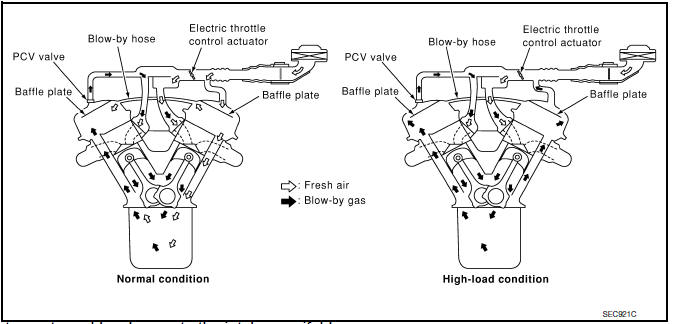
This system returns blow-by gas to the intake manifold.
The positive crankcase ventilation (PCV) valve is provided to conduct crankcase blow-by gas to the intake manifold.
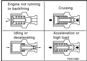
During partial throttle operation of the engine, the intake manifold sucks the blow-by gas via the PCV valve.
Normally, the capacity of the valve is sufficient to handle any blow-by and a small amount of ventilating air.
The ventilating air is drawn from the air inlet tubes into the crankcase. In this process the air passes via the hose connecting air inlet tubes to rocker cover.
Under full-throttle condition, the manifold vacuum is insufficient to draw the blow-by flow via the valve.
The flow goes via the hose connection in the reverse direction.
On vehicles with an excessively high blow-by, the valve does not meet the requirement. This is because some of the flow will go via the hose connection to the air inlet tubes under all conditions.
Component Inspection
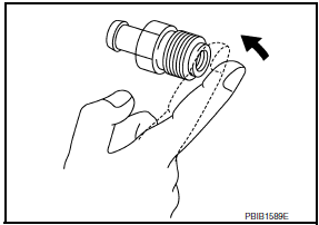
1.CHECK PCV VALVE
With engine running at idle, remove PCV valve from rocker cover. A properly working valve makes a hissing noise as air passes via the it.
A strong vacuum should be felt immediately when a finger is placed over valve inlet.
 On board refueling vapor recovery (ORVR)
Description
From the beginning of refueling, the air and vapor inside the fuel tank go
via the refueling EVAP vapor cut
valve and EVAP/ORVR line to the EVAP canister. The vapor is absorbed by ...
 Refrigerant pressure sensor
Description
The refrigerant pressure sensor is installed at the condenser of the air
conditioner system. The sensor uses an
electrostatic volume pressure transducer to convert refrigerant pressur ...
Other materials:
DLC branch line circuit
Diagnosis Procedure
1.CHECK CONNECTOR
Turn the ignition switch OFF.
Disconnect the battery cable from the negative
terminal.
Check the terminals and connectors of the data
link connector for damage, bend and loose connection
(connector side and harn ...
The braking distance is long
Diagnosis Procedure
CAUTION:
The stopping distance on slippery road surfaces might be longer with the ABS
operating than when
the ABS is not operating.
1.CHECK FUNCTION
Turn ignition switch OFF and disconnect ABS actuator and electric unit
(control unit) connector to deactivate
ABS. In ...
Spiral cable
Removal and Installation
CAUTION:
Before servicing, turn ignition switch OFF, disconnect both
battery terminals and wait at least 3 minutes.
Do not use air tools or electric tools for servicing.
Do not disassemble the spiral cable.
Do not allow oil, grease, detergent or water to come ...
Nissan Maxima Owners Manual
- Illustrated table of contents
- Safety-Seats, seat belts and supplemental restraint system
- Instruments and controls
- Pre-driving checks and adjustments
- Monitor, climate, audio, phone and voice recognition systems
- Starting and driving
- In case of emergency
- Appearance and care
- Do-it-yourself
- Maintenance and schedules
- Technical and consumer information
Nissan Maxima Service and Repair Manual

0.0069