Nissan Maxima Owners Manual: Navigation System
Turn-by-turn route guidance can be displayed on the vehicle information display.
To view turn-by-turn route guidance on the vehicle
information display, use  or
or
 and
scroll to
and
scroll to on the vehicle
information display
menu.
on the vehicle
information display
menu.
City view
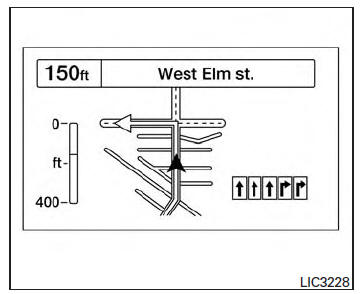
City view shows representation of intersections with road curvature and surroundings.
Lane guidance will appear in the lower right corner if the data is available for that street. The next turn and the distance to the next turn are displayed on the vehicle information display. A countdown bar is shown in the arrow. The bar gets smaller as you get closer to the next turn.
Arrow view
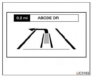
Lane guidance will appear in the lower right corner, if the data is available for that street.
A turn direction arrow with an icon indicating your current route location is displayed. A countdown bar will be shown on the left side of the vehicle information display. The bar gets smaller as you get closer to the next turn.
Compass view
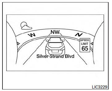
Compass view is displayed when no route is set, and shows current weather conditions and speed limit information (if available).
Far screen view
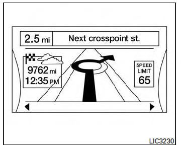
Far screen view shows destination information, weather and speed limit information (if available for the street).
Navigation settings
The navigation related display settings can be changed.
1. Select  using
using
 or
or
 and
press the OK button. A menu will display.
and
press the OK button. A menu will display.
2. Using  or
or
 , select [Customize
Display] and then select [Navigation Settings].
, select [Customize
Display] and then select [Navigation Settings].
3. Select the preferred item using  or
or  .
.
| Available items | Action |
| [Alerts] | When this item is turned on, the view of the turning point with an alarm sound will interrupt the displays other than navigation screen when the vehicle approaches the guide point. |
| [Arrow view] | When this mode is selected, the Arrow view will be displayed on the vehicle information display |
| [City view] | When this mode is selected, the view on the vehicle information display will switch from the Arrow view to the City view as the vehicle approaches a guide point. |
4. Press the OK button to turn on or off the [Alerts] setting or to toggle the view mode between [Arrow] or [City].
 Text Messaging
Using the Bluetooth Hands-Free Phone System,
a received text message can be operated on
the vehicle information display as well as on the
touch-screen display.
To read/ignore an incoming text
1. ...
 Navigation Swipe to Meter
Turn-by-turn route guidance can also be viewed
in the vehicle information display by using Navigation
Swipe to Meter. This can be done by
programming a route, touching the turn-by-turn
route i ...
Other materials:
Magnet clutch control system
System Diagram
System Description
The A/C auto amp. controls A/C compressor operation by ambient temperature,
intake air temperature and
signal from ECM.
SYSTEM OPERATION
When the A/C switch, the AUTO switch, or the DEF switch is pressed, or when
shifting mode position to D/F,
the A/C ...
NISSAN Intelligent Key
WARNING
Radio waves could adversely affect
electric medical equipment. Those who
use a pacemaker should contact the
electric medical equipment manufacturer
for the possible influences before
use.
The Intelligent Key transmits radio
waves when the buttons are pressed.
The FAA ad ...
Heater & cooling unit assembly
Exploded View
Wiring harness
Mode door motor
Upper floor connecting duct (LH)
Air mix door motor (driver side)
Heater core pipes cover
Heater core
In-cabin microfilter
Filter cover
Blower motor
Intake door motor
Blower unit
Upper floor connecting duct (RH)
Air mi ...
Nissan Maxima Owners Manual
- Illustrated table of contents
- Safety-Seats, seat belts and supplemental restraint system
- Instruments and controls
- Pre-driving checks and adjustments
- Monitor, climate, audio, phone and voice recognition systems
- Starting and driving
- In case of emergency
- Appearance and care
- Do-it-yourself
- Maintenance and schedules
- Technical and consumer information
Nissan Maxima Service and Repair Manual

0.0071