Nissan Maxima Service and Repair Manual: Automatic drive positioner system
AUTOMATIC DRIVE POSITIONER SYSTEM : System Diagram
AUTOMATIC DRIVE POSITIONER SYSTEM : System Description
OUTLINE
The system automatically moves the driver seat, steering column and door mirror position by the driver seat control unit and the automatic drive positioner control unit. The driver seat control unit corresponds with the automatic drive positioner control unit by UART communication.
| Function | Description | |
| Manual function | The driving position (seat, steering column and door mirror position) can be adjusted by using the power seat switch, ADP steering switch or door mirror remote control switch | |
| Memory function | The seat, steering column and door mirror move to the stored driving position by pressing seat memory switch (1 or 2). | |
| Entry/Exit assist function | Exit | On exit, the seat moves backward and the steering column moves upward |
| Entry | On entry, the seat and steering column returns from exiting position to the previous driving position | |
| Intelligent Key interlock function | Perform memory operation, exiting operation and entry operation by Intelligent Key unlock operation or driver side door request switch unlock operation | |
NOTE: The lumbar support system is controlled independently with no link to the automatic drive positioner system.
AUTOMATIC DRIVE POSITIONER SYSTEM : Component Parts Location
- Push-button ignition switch M38
- BCM M16, M17, M18, M19 (view with instrument panel removed)
- TCM F15
- A. ADP steering switch M39 B. Tilt motor M71, telescopic motor M73
- A. Power seat switch LH B213 B. Reclining motor B222 C. Driver seat control unit B203, B211
- Automatic drive positioner control unit M63, M67 (view with instrument panel removed)
- A. Door mirror LH D4
B. Door mirror RH D107
C. Front door switch LH B8 - Door mirror remote control switch M108
- Seat memory switch D13
 : Front
AUTOMATIC DRIVE POSITIONER SYSTEM : Component Description
CONTROL UNITS
| Item | Function |
| Driver seat control unit |
|
| Automatic drive positioner control uni |
|
| BCM |
Transmits the following status to the driver seat control unit via CAN communication.
|
| Combination meter | Transmits the vehicle speed signal to the driver seat control unit via CAN communicati |
| AV control unit | The setting change of auto drive positioner system can be performed on the display |
| TCM | Transmits the shift position signal (P range) to the driver seat control unit via CAN communication. |
INPUT PARTS
Switches
| Item | Function |
| Key slot | The key switch is installed to detect the key inserted/removed status. |
| Front door switch LH | Detect front door (driver side) open/close status. |
| Transmission range switch (built into CVT control valve assembly) | Detect the P range position of CVT selector lever. |
| Set swi | The registration and system setting can be performed with its operation |
| Seat memory switch 1/2 | The registration and operation can be performed with its operation. |
| Power seat switch |
The following switch is installed.
The specific parts can be operated with the operation of each s |
| ADP steering switch |
The following switch is installed.
The specific parts can be operated with the operation of each switch. |
| Door mirror remote control switch |
The following switch is installed.
The specific parts can be operated with the operation of each switch. |
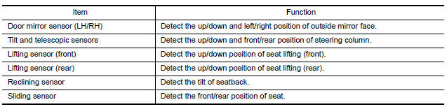
Sensors
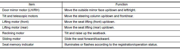
OUTPUT PARTS

 Manual function
MANUAL FUNCTION : System Diagram
MANUAL FUNCTION : System Descriptio
OUTLINE
The driving position (seat, steering column and door mirror position) can be
adjusted manually with power seat swi ...
Other materials:
Turn signal and hazard warning lamps
System Diagram
System Description
BCM (Body Control Module) controls turn signal lamp (RH and LH) and
hazard warning lamp operation.
Combination meter operates turn signal indicator (RH and LH) according
to CAN communication signals from BCM.
Component Parts Location
BCM M1 ...
Rear disc brake
Exploded View of Brake Pads
Inner shim cover
Inner shim
Inner pad
Pad retainer
Outer pad
Outer shim
Outer shim cover
Molykote AS-880N grease
Molykote 7439 grease
Removal and Installation of Brake Pads
WARNING:
Clean dust on caliper and brake pad with a vacuum dust ...
Wiring diagram
WARNING CHIME SYSTEM
Wiring Diagram
...
Nissan Maxima Owners Manual
- Illustrated table of contents
- Safety-Seats, seat belts and supplemental restraint system
- Instruments and controls
- Pre-driving checks and adjustments
- Monitor, climate, audio, phone and voice recognition systems
- Starting and driving
- In case of emergency
- Appearance and care
- Do-it-yourself
- Maintenance and schedules
- Technical and consumer information
Nissan Maxima Service and Repair Manual

0.0055