Nissan Maxima Service and Repair Manual: ECU diagnosis information
CLIMATE CONTROLLED SEAT CONTROL UNIT
Reference Value
TERMINAL LAYOUT
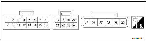
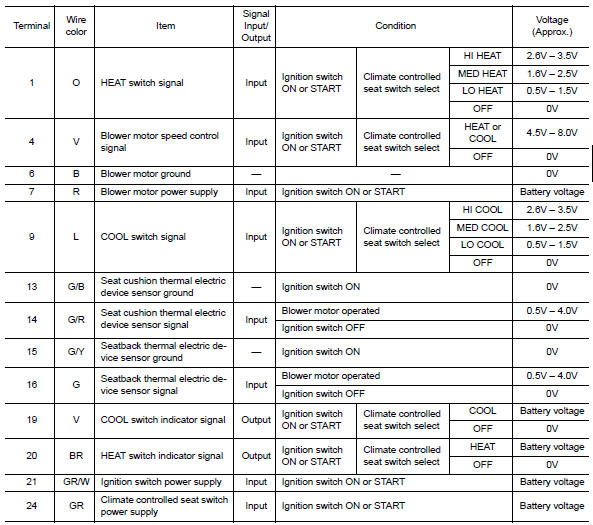
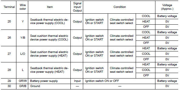
PHYSICAL VALUES
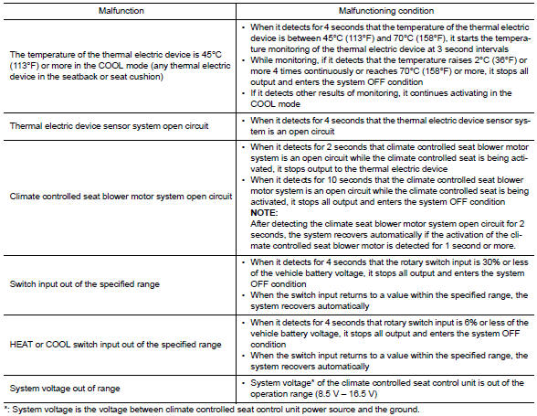
Fail-safe
- Climate controlled seat control unit equips fail-safe function.
- When a malfunction occurs in the systems shown as per the following, climate controlled seat control unit stops output.
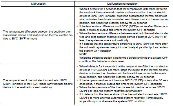
NOTE:
When the system enters in the fail-safe mode again after performing resetting procedure, perform diagnosis.
 Climate controlled seat switch indicator
Description
Illuminates the climate controlled seat switch to indicate operating status.
Component Function Check
1.CHECK CLIMATE CONTROLLED SEAT SWITCH INDICATOR FUNCTION
Check that the indicator ...
 Wiring diagram
...
Other materials:
U1000 CAN comm circuit
Description
CAN (Controller Area Network) is a serial communication line for real time
application. It is an on-vehicle multiplex
communication line with high data communication speed and excellent malfunction
detection ability.
Many electronic control units are equipped onto a vehicle, an ...
Interior trunk lid release
WARNING
Closely supervise children when they are
around cars to prevent them from playing
and becoming locked in the trunk where
they could be seriously injured. Keep the
car locked, with the rear seatback and
trunk lid securely latched when not in use,
and prevent children's access to ca ...
Trunk lid
WARNING
Do not drive with the trunk lid open. This
could allow dangerous exhaust gases
to be drawn into the vehicle. For additional
information, refer to "Exhaust
gas (carbon monoxide)" in the "Starting
and driving" section of this manual.
Closely supervise children when they
are a ...
Nissan Maxima Owners Manual
- Illustrated table of contents
- Safety-Seats, seat belts and supplemental restraint system
- Instruments and controls
- Pre-driving checks and adjustments
- Monitor, climate, audio, phone and voice recognition systems
- Starting and driving
- In case of emergency
- Appearance and care
- Do-it-yourself
- Maintenance and schedules
- Technical and consumer information
Nissan Maxima Service and Repair Manual

0.0053