Nissan Maxima Service and Repair Manual: Brake pedal
Exploded View
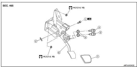
- Clevis pin
- Snap pin
- Stop lamp switch
- ASCD cancel switch
- Clip
- Brake pedal assembly
- Brake pedal pad
NOTE: The clevis pin must be installed from the RH side as shown.
Removal and Installation
REMOVAL
- Remove instrument lower panel LH and lower knee protector. Refer to IP-10, "Exploded View".
- Remove the accelerator pedal assembly. Refer to ACC-3, "Removal and Installation".
- Disconnect the harness connectors from the stop lamp switch and ASCD cancel switch.
- Remove stop lamp switch and ASCD cancel switch from brake pedal assembly.
- Remove snap pin and clevis pin from brake booster clevis.
- Disconnect the steering column upper joint and reposition it out of the way.
- Remove brake pedal assembly to brake booster nuts. Pull brake booster toward engine room to the extent that does not deform the brake tubes.
WARNING: Do not bend the brake tube.
- Remove brake booster clevis from input rod.
- Remove top nut and then remove brake pedal assembly.
- Temporarily install the brake pedal assembly to brake booster nuts by hand to support the brake booster.
CAUTION: Avoid damage from dropping the brake pedal assembly during handling.
INSPECTION AFTER REMOVAL
Check the brake assembly for the following items:
- Crack or deformation of the clevis pin.
- Crack of any welded portion of the brake pedal assembly.
- Brake pedal bend or deformation.
INSTALLATION
Installation is in the reverse order of removal.
- Check the brake pedal for smooth operation. There should be no binding or sticking when applying or releasing the brake pedal.
- Adjust brake pedal height after installing brake pedal assembly. Refer to BR-14, "Inspection and Adjustment".

 Brake tube and hose
Hydraulic Circuit
Actuator
Master cylinder
Brake booster
Connector A. Union bolt
18.2 N*m (1.9 kg-m, 13 ft-lb)
B. Flare nut M12
22.1 N*m (2.3 kg-m, 16 ft-lb)
C. Flare nut M ...
Other materials:
CVT system
System Diagram
Component Parts Location
CVT shift selector assembly (Manual
mode select switch and manual
mode position select switch)
Secondary speed sensor
CVT unit harness connector
TCM
Accelerator pedal position (APP)
sensor
Stop ...
Sunshade motor assembly
Removal and Installation
REMOVAL
CAUTION:
Before removing sunshade motor, check that glass lid is fully
closed.
After removing sunshade motor, do not attempt to rotate
sunshade motor assembly as a single unit
Close glass lid.
Remove the headlining. Refer to INT-33, "Removal and ...
Vehicle speed signal circuit
Description
Combination meter sends vehicle speed signal to power steering control unit.
Diagnosis Procedure
1.PERFORM COMBINATION METER SELF-DIAGNOSIS
Perform combination meter self-diagnosis.
2.CHECK HARNESS BETWEEN COMBINATION METER AND POWER STEERING CONTROL UNIT FOR
OPEN
Turn the ...
Nissan Maxima Owners Manual
- Illustrated table of contents
- Safety-Seats, seat belts and supplemental restraint system
- Instruments and controls
- Pre-driving checks and adjustments
- Monitor, climate, audio, phone and voice recognition systems
- Starting and driving
- In case of emergency
- Appearance and care
- Do-it-yourself
- Maintenance and schedules
- Technical and consumer information
Nissan Maxima Service and Repair Manual

0.0073