Nissan Maxima Service and Repair Manual: P0841 transmission fluid pressure SEN/SW A
Description
Using the engine load (throttle position), the primary pulley revolution speed, and the secondary pulley revolution speed as input signals, TCM changes the operating pressure of the primary pulley and the secondary pulley and changes the groove width of the pulley to control the gear ratio.
DTC Logic
DTC DETECTION LOGIC

DTC CONFIRMATION PROCEDURE
CAUTION: Always drive vehicle at a safe speed.
NOTE: Immediately after performing any "DTC CONFIRMATION PROCEDURE", always turn ignition switch OFF.
Then wait at least 10 seconds before performing the next test.
1.CHECK DTC DETECTION
 With CONSULT
- Turn ignition switch ON.
- Select "Data Monitor" in "TRANSMISSION".
- Start engine and maintain the following conditions for at least 12 consecutive seconds.
VEHICLE SPEED : 40 km/h (25 MPH) or more
RANGE : "D" position
Diagnosis Procedure
1.CHECK LINE PRESSURE
Perform line pressure test. Refer to TM-162, "Inspection and Judgment".
2.CHECK SECONDARY PRESSURE SENSOR SYSTEM
Check secondary pressure sensor system. Refer to TM-85, "Description".
3.CHECK PRIMARY PRESSURE SENSOR SYSTEM
Check primary pressure sensor system. Refer to TM-90, "Description".
4.CHECK LINE PRESSURE SOLENOID VALVE
- Turn ignition switch OFF.
- Disconnect CVT unit connector.
- Check line pressure solenoid valve. Refer to TM-89, "Component Inspection (Line Pressure Solenoid Valve)".
5.CHECK SECONDARY PRESSURE SOLENOID VALVE
Check secondary pressure solenoid valve. Refer to TM-89, "Component Inspection (Secondary Pressure Solenoid Valve)".
6.CHECK STEP MOTOR SYSTEM
Check step motor system. Refer to TM-109, "Description".
7.DETECT MALFUNCTIONING ITEMS
Check TCM connector pin terminals for damage or loose connection with harness connector.
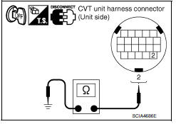
Component Inspection (Line Pressure Solenoid Valve)
1.CHECK LINE PRESSURE SOLENOID VALVE
Check resistance between CVT unit connector terminal and ground.


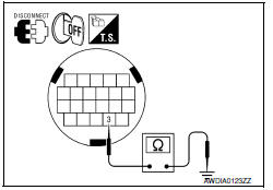
Component Inspection (Secondary Pressure Solenoid Valve)
1.CHECK SECONDARY PRESSURE SOLENOID VALVE
Check resistance between CVT unit connector terminal and ground.


 P0840 transmission fluid pressure SEN/SW A
The secondary pressure sensor detects secondary pressure of CVT and sends a
signal to the TCM.
DTC Logic
DTC DETECTION LOGIC
DTC CONFIRMATION PROCEDURE
NOTE:
Immediately after performing any ...
 P0845 transmission fluid pressure SEN/SW B
Description
The primary pressure sensor detects primary pressure of CVT and sends a
signal to the TCM.
DTC Logic
DTC DETECTION LOGIC
DTC CONFIRMATION PROCEDURE
NOTE:
Immediately after perfo ...
Other materials:
ECM branch line circuit
Diagnosis Procedure
1.CHECK CONNECTOR
Turn the ignition switch OFF.
Disconnect the battery cable from the negative
terminal.
Check the following terminals and connectors
for damage, bend and loose connection (unit side and connector
side).
&nb ...
Lighting & turn signal switch
Removal and Installation
NOTE: The lighting and turn signal switch is
integral with the combination switch assembly.
REMOVAL
Unlock steering wheel.
CAUTION:
Before servicing, disconnect both battery terminals and wait
at least three minutes
Do not use air tools or electric tools ...
Microphone signal circuit
Description
Voice signals are transmitted from the microphone to the Bluetooth control
unit using the microphone signal circuits.
Diagnosis Procedure
1.CHECK HARNESS BETWEEN BLUETOOTH CONTROL UNIT AND MICROPHONE
Turn ignition switch OFF.
Disconnect Bluetooth control unit connector and ...
Nissan Maxima Owners Manual
- Illustrated table of contents
- Safety-Seats, seat belts and supplemental restraint system
- Instruments and controls
- Pre-driving checks and adjustments
- Monitor, climate, audio, phone and voice recognition systems
- Starting and driving
- In case of emergency
- Appearance and care
- Do-it-yourself
- Maintenance and schedules
- Technical and consumer information
Nissan Maxima Service and Repair Manual
0.0071
