Nissan Maxima Service and Repair Manual: Power supply routing circuit
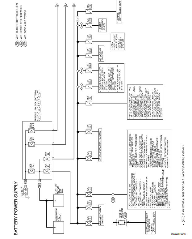
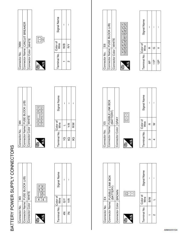
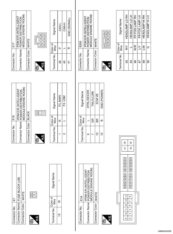
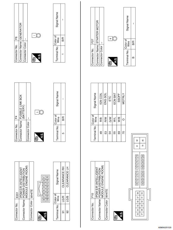
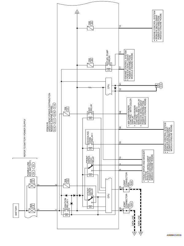
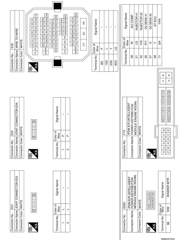
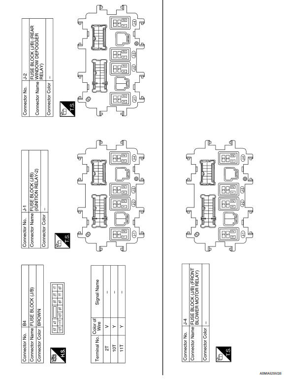
Wiring Diagram -Battery Power Supply -
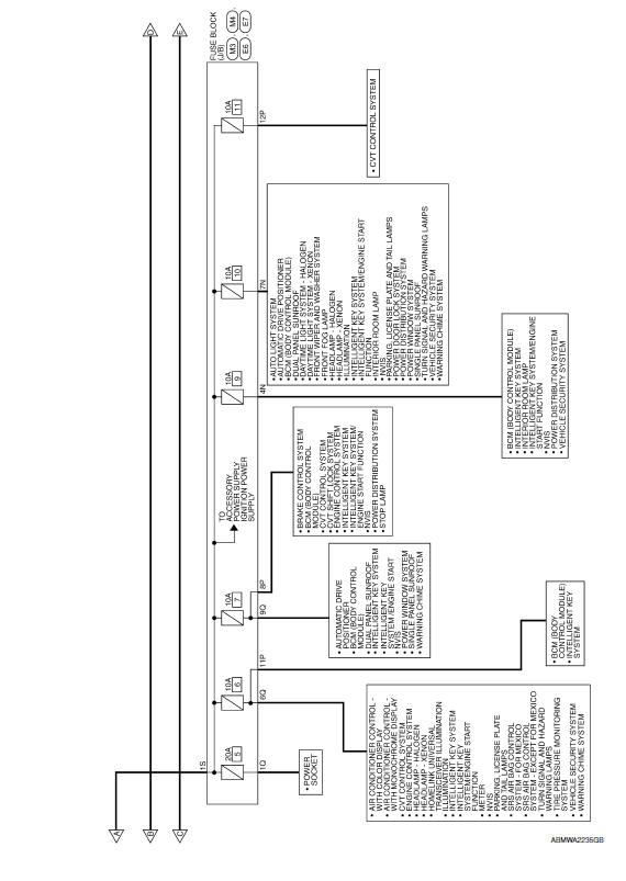
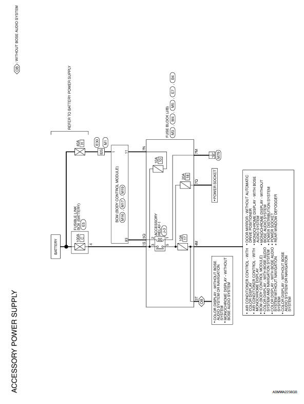
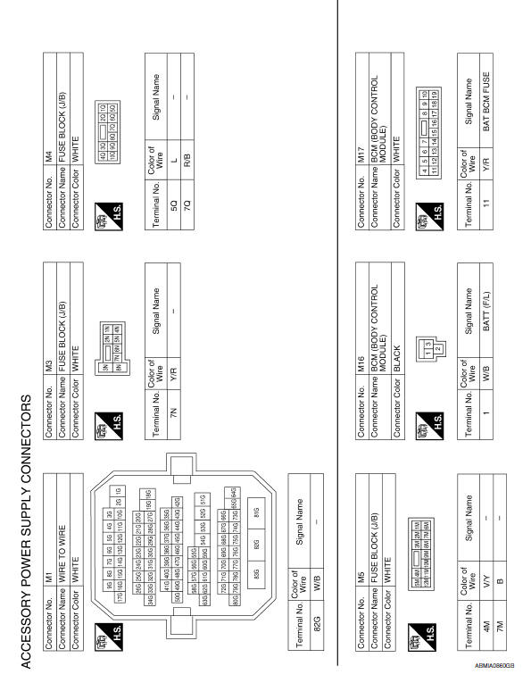
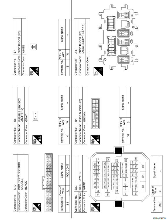
Wiring Diagram -Accessory Power Supply -
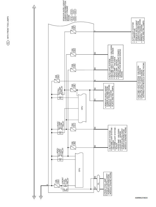
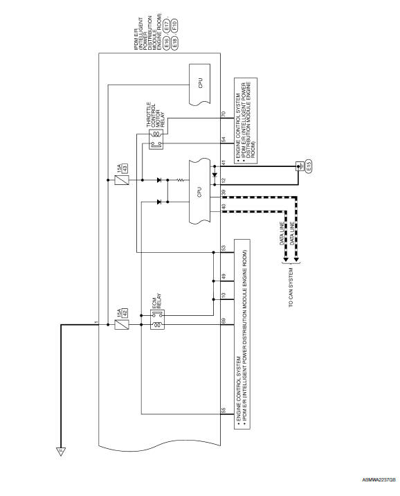
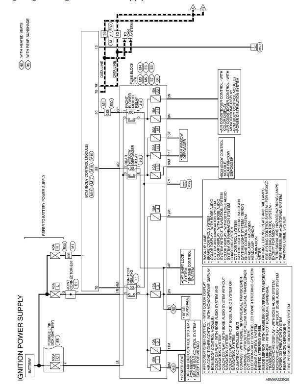
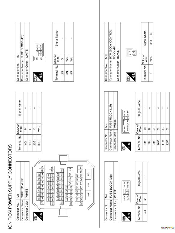
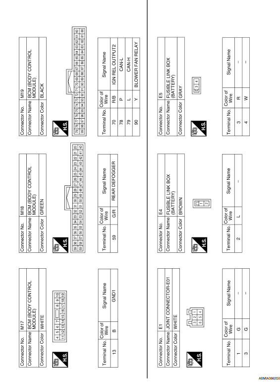
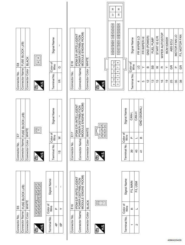
Wiring Diagram -Ignition Power Supply -
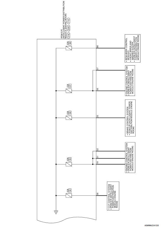
Fuse
- If fuse is blown, be sure to eliminate cause of malfunction before installing new fuse.
- Use fuse of specified rating. Never use fuse of more than specified rating.
- Do not partially install fuse; always insert it into fuse holder properly.
- Remove fuse for "ELECTRICAL PARTS (BAT)" if vehicle is not used for a long period of time.
Fusible Link
A melted fusible link can be detected either by visual inspection or by feeling with finger tip. If its condition is questionable, use circuit tester or test lamp.
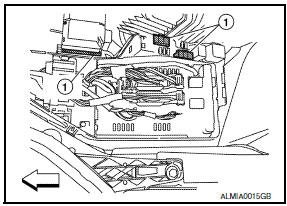
1 : Fusible link
CAUTION:
- If fusible link should melt, it is possible that critical circuit (power supply or large current carrying circuit) is shorted. In such a case, carefully check and eliminate cause of malfunction.
- Never wrap outside of fusible link with vinyl tape. Important: Never let fusible link touch any other wiring harness, vinyl or rubber parts.

 Ground
Ground Distribution
MAIN HARNESS
ENGINE ROOM HARNESS
FRONT END MODULE HARNESS
ENGINE CONTROL HARNESS
BODY HARNESS
BODY NO. 2 HARNESS
...
Other materials:
B2130 eeprom
DTC Logic
DTC DETECTION LOGIC
DTC No.
Trouble diagnosis name
DTC detecting condition
Possible cause
B2130
EEPROM
Driver seat control unit detected CPU malfunction
Driver seat control unit
DTC CONFIRMATION PROCEDURE
1. PERFORM DTC CONFIRMATI ...
Climate controlled seat switches (if so equipped)
The climate controlled seat warms up or cools
down the front seat by blowing warm or cool air
from under the surface of the seat. The climate
control switch is located on the center console.
The climate controlled seat can be operated as
follows:
1. Start the engine.
2. Turn the contr ...
Trunk lid opener
Wiring Diagram
...
Nissan Maxima Owners Manual
- Illustrated table of contents
- Safety-Seats, seat belts and supplemental restraint system
- Instruments and controls
- Pre-driving checks and adjustments
- Monitor, climate, audio, phone and voice recognition systems
- Starting and driving
- In case of emergency
- Appearance and care
- Do-it-yourself
- Maintenance and schedules
- Technical and consumer information
Nissan Maxima Service and Repair Manual

0.0053