Nissan Maxima Service and Repair Manual: Steering gear and linkage
Exploded View
- Outer socket
- Boot clamp
- Boot
- Inner socket
- Boot clamp
- SSPS valve (part of gear assembly)
- Gear assembly
Front
Three Bond 1111B or equivalent
Disassembly
- Remove outer socket locknut and outer socket.
- Remove boot clamps and boot. CAUTION: Do not reuse boot clamps.
- Remove inner socket.
Inspection
INSPECTION AFTER DISASSEMBLY
Boot
Check boot for cracks. Replace if any damage is found.
Outer Socket and Inner Socket
- Ball joint swinging torque
- Hook a spring balance to the ball stud and inner socket measuring point (*) and pull the spring balance. Make sure that the spring balance reads the specified value when ball stud and inner socket start to move. Replace outer socket and steering gear assembly if they are outside the standard.
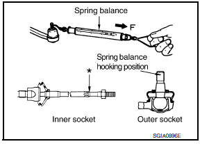
Tool number : - (J-44372)
- Ball joint rotating torque
- Make sure that the reading is within the following specified range using Tool. Replace outer socket if the reading is outside the specified value.
Tool number : ST3127S000 (J-25765-A)
- Ball joint axial end play
- Apply an axial load of 490 N (50 kg, 111 lb) to ball stud. Measure amount of stud movement using a dial gauge and then make sure that the value is within the following specified range. Replace outer socket and inner socket if the measured value is outside the standard.
Assembly
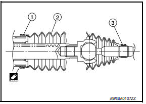
- Apply Three Bond 1111B or equivalent to inner socket and turn pinion fully to retract inner socket into gear housing assembly.
- Install large end (1) of boot (2) to gear housing assembly.
- Install small end (3) of boot (2) to inner socket boot mounting groove.
- Install boot clamp to boot small end. CAUTION: Do not reuse boot clamps.
- Install boot clamp to boot large end using Tool. CAUTION: Do not reuse boot clamps.
Tool number : KV40107300 ( - )
- Adjust inner socket to standard length (L), and then tighten lock nut to the specified torque. Check length of inner socket (L) again after tightening lock nut. Make sure that the length is the standard.
CAUTION: Adjust toe-in after this procedure. The length achieved after toe-in adjustment is not necessarily the above value.
POWER STEERING OIL PUMP
Disassembly and Assembly
The power steering oil pump and pulley is not serviceable and should be replaced as an assembly. For front and rear bracket removal
 Steering column
Disassembly and Assembly
The steering column assembly without electric motor is not serviceable and
must be replaced as an assembly.
With Electric Motor
Steering column assembly
Telesco ...
 Service data and specifications (SDS)
Steering Wheel
Steering Angle
Steering Column
STEERING COLUMN LENGTH
STEERING COLUMN ROTATING TORQUE
TILT MECHANISM OPERATING RANGE
Steering Gear
STEERING OUTER SOCKET AND INNER ...
Other materials:
B1086 - B1089 seat belt pre-tensioner LH
Description
DTC B1086 - B1089 SEAT BELT PRE-TENSIONER LH
The seat belt pre-tensioner LH is wired to the air bag diagnosis sensor unit.
The air bag diagnosis sensor unitwill monitor for opens and shorts in
detected lines to the seat belt pre-tensioner LH.
PART LOCATION
DTC Logic
DTC DETECTIO ...
Locking with power door lock switch
To lock all the doors without a key, push the door
lock switch (driver's or front passenger's side) to
the lock position 1 . When locking the door this
way, be certain not to leave the key inside the
vehicle.
To unlock all the doors without a key, push the
door lock switch (driver's or f ...
Precaution
Precaution for Supplemental Restraint System (SRS) "AIR BAG" and "SEAT
BELT
PRE-TENSIONER"
The Supplemental Restraint System such as "AIR BAG" and "SEAT BELT PRE-TENSIONER",
used along
with a front seat belt, helps to reduce the risk or severity of injury to the
driver ...
Nissan Maxima Owners Manual
- Illustrated table of contents
- Safety-Seats, seat belts and supplemental restraint system
- Instruments and controls
- Pre-driving checks and adjustments
- Monitor, climate, audio, phone and voice recognition systems
- Starting and driving
- In case of emergency
- Appearance and care
- Do-it-yourself
- Maintenance and schedules
- Technical and consumer information
Nissan Maxima Service and Repair Manual

0.0055