Nissan Maxima Service and Repair Manual: Sunroof system
System Diagr
SUNROOF
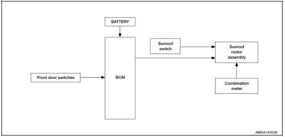
System Description
SUNROOF SYSTEM
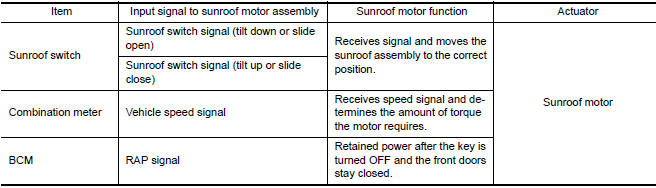
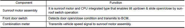
INPUT/OUTPUT SIGNAL CHART
SUNROOF OPERATION
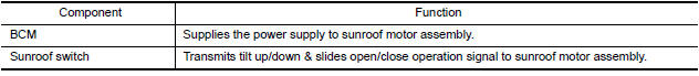
- Sunroof motor assembly operates with the power supply that is output from BCM while ignition switch is ON or retained power is operating.
- Tilt up/ down & slide open/ close signals from sunroof switch enable sunroof motor to move arbitrarily.
- Sunroof motor assembly receives a vehicle speed signal from combination meter and controls the sunroof motor torque of tilt down at the time of high speed operation.
AUTO OPERATION
Sunroof AUTO feature makes it possible to slide open and slide close or tilt up and tilt down the sunroof without holding the sunroof switch in the slide open/tilt down or slide close/tilt up position.
RETAINED POWER OPERATION
- Retained power operation is an additional power supply function
that enables the sunroof system to operate during 45 seconds, even when
ignition switch is turned OFF.
Retained power function cancel conditions
- Door CLOSE (door switch OFF)→OPEN (door switch ON).
- When ignition switch is ON again.
- When timer time passes (45 seconds).
ANTI-PINCH FUNCTION
The CPU of sunroof motor assembly monitors the sunroof motor operation and the sunroof position (fullyclosed or other) by the signals from sunroof motor.
When sunroof motor detects an interruption during the following slide close and tilt down operation, sunroof switch controls the motor for open and the sunroof will operate until full up position (when tilt down operates) or 150 mm (5.91 in) or more in an open direction (when slide close operates):
- close operation and tilt down when ignition switch is in the "ON" position
Component Parts Location
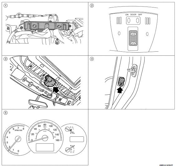
- BCM M16, M17, M18 (view with instrument panel removed)
- Sunroof switch R6
- Sunroof motor assembly R5
- Front door switch LH B8, RH B108
- Combination meter M24
Component Description

 Diagnosis system (BCM)
COMMON ITEM
COMMON ITEM : CONSULT Function (BCM - COMMON ITEM
APPLICATION ITEM
CONSULT performs the following functions via CAN communication with BCM.
SYSTEM APPLICATION
BCM can perform the fo ...
Other materials:
Satellite radio antenna
Removal and Installation
REMOVAL
Lower the headlining at the rear. Refer to INT-33, "Exploded
View".
Disconnect the harness connector (A) from satellite radio
antenna.
Remove the satellite radio antenna nut (B) and the satellite radio
antenna (1).
INSTALLATION
Ins ...
Daytime running light system
The LED portion of the headlights automatically
illuminate at 100% intensity when the engine is
started and the parking brake released. The daytime
running lights operate with the headlight
switch in the OFF position. When you turn the
headlight switch to the position for
full
illumination t ...
BCM (body control module)
Reference Value
NOTE: The Signal Tech II Tool (J-50190) can
be used to perform the following functions. Refer to the Signal Tech II User
Guide for additional information.
Activate and display TPMS transmitter IDs
Display tire pressure reported by the TPMS transmitter
Read TPMS DTCs
Re ...
Nissan Maxima Owners Manual
- Illustrated table of contents
- Safety-Seats, seat belts and supplemental restraint system
- Instruments and controls
- Pre-driving checks and adjustments
- Monitor, climate, audio, phone and voice recognition systems
- Starting and driving
- In case of emergency
- Appearance and care
- Do-it-yourself
- Maintenance and schedules
- Technical and consumer information
Nissan Maxima Service and Repair Manual

0.0066