Nissan Maxima Service and Repair Manual: Steering column
Disassembly and Assembly
The steering column assembly without electric motor is not serviceable and must be replaced as an assembly.
With Electric Motor
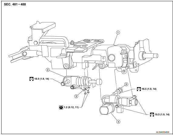
- Steering column assembly
- Telescope motor
- Telescope motor link bracket
- Tilt motor
- Tilt motor bolt cap
DISASSEMBLY
- Remove the steering wheel. Refer to ST-17, "Removal and Installation".
Tilt motor
- Remove the tilt motor as follows.
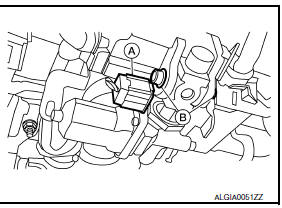
- Disconnect the harness connector (A) from the tilt motor.
- Remove the tilt motor link bolts (B).
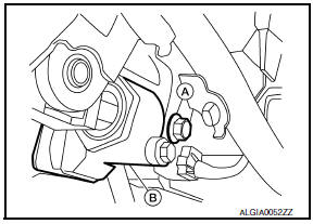
- Remove the tilt motor bolt (A) from the RH side of column.
- Remove the tilt motor (B).
NOTE: If the steering wheel could not be tilted to the highest position, manually tilt steering wheel to the highest position.
Telescope motor
- Remove telescope motor as follows.
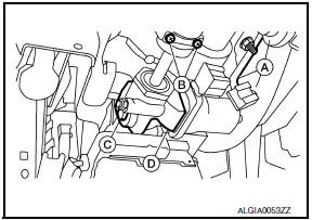
- Disconnect the harness connector (A) from the telescope motor.
- Remove the two telescope motor link screws (B) and telescope motor link bracket.
- Remove telescope motor bolt (C).
- Remove the telescope motor (D).
NOTE: If the steering wheel could not be telescoped to full out position manually pull steering wheel to the full out position
ASSEMBLY
Assembly is in the reverse order of removal
NOTE:
- Upon installation of the tilt motor link bolts manually move steering wheel up and down to align the bolts.
- Adjust the telescope motor link to full out position and adjust as needed to fit into proper installed position.
- Inform customer that they will need to reset their Automatic Drive Positioner (ADP) settings.

 Steering gear and linkage
Exploded View
Outer socket
Boot clamp
Boot
Inner socket
Boot clamp
SSPS valve (part of gear assembly)
Gear assembly Front Three Bond 1111B or equivalent
Disassembly
Remove ...
Other materials:
P1615 diffrence of key
Description
Performs ID verification through BCM and Intelligent Key
when push-button ignition switch is pressed.
Prohibits the start of engine when an unregistered ID of Intelligent Key is
used.
DTC Logic
DTC DETECTION LOGIC
DTC CONFIRMATION PROCEDURE
1.PERFORM DTC CONFIRMATION PROCED ...
Unit disassembly and assembly
COOLING FAN
Disassembly and Assembly of Cooling Fan
Fan blade
Fan shroud
Fan motor
DISASSEMBLY
Remove fan blade nut.
Remove fan blade from fan motor.
Remove fan motor bolts and remove fan motor from fan shroud.
ASSEMBLY
Assembly is in the reverse order of disassembly. ...
P1572 ASCD brake switch
Description
When the brake pedal is depressed, ASCD brake switch is turned OFF and stop
lamp switch is turned ON.
ECM detects the state of the brake pedal by those two types of input (ON/OFF
signal).
Refer to EC-68, "System Diagram" for the ASCD function.
DTC Logic
DTC DETECTI ...
Nissan Maxima Owners Manual
- Illustrated table of contents
- Safety-Seats, seat belts and supplemental restraint system
- Instruments and controls
- Pre-driving checks and adjustments
- Monitor, climate, audio, phone and voice recognition systems
- Starting and driving
- In case of emergency
- Appearance and care
- Do-it-yourself
- Maintenance and schedules
- Technical and consumer information
Nissan Maxima Service and Repair Manual

0.0051