Nissan Maxima Owners Manual: Engine compartment check locations
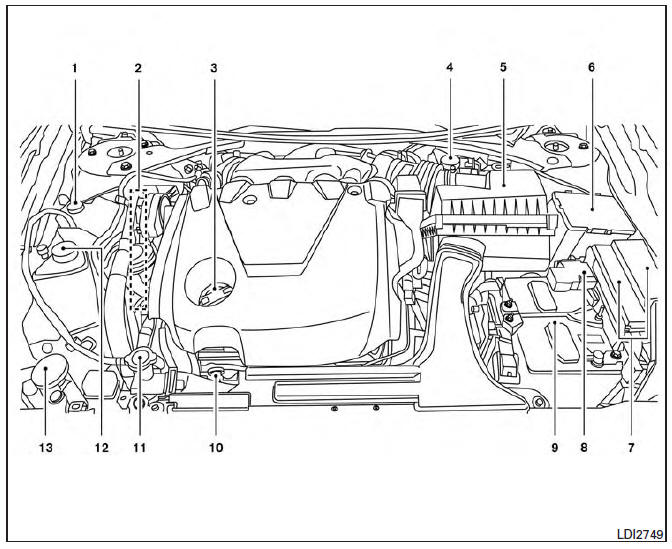
VQ35DE engine
- Engine coolant reservoir
- Drive belt location
- Engine oil filler cap
- Brake fluid reservoir
- Air cleaner
- Fuse block
- Fuse block/Fusible links
- Fusible links
- Battery
- Engine oil dipstick
- Radiator cap
- Power steering fluid reservoir
- Windshield-washer fluid reservoir
Refer to the page number indicated in parentheses for operating details.
Warning and indicator lights
| Warning light | Name |
 |
Anti-lock Braking System (ABS) warning light |
 |
Brake warning light (parking brake) |
 |
Brake warning light |
 |
Charge warning light |
 |
Engine oil pressure warning light |
 |
Forward Emergency Braking (FEB) system warning light (if so equipped) |
 |
Low tire pressure warning light |
 |
Master warning light |
 |
Power steering warning light |
 |
Seat belt warning light and chime |
 |
Supplemental air bag warning light |
| Indicator light | Name |
 |
Front fog light indicator light (green) |
 |
Front passenger air bag status light |
 |
High beam indicator light (blue) |
 |
Malfunction Indicator Light (MIL) |
 |
Security indicator light |
 |
Side light and headlight indicator light (green) |
 |
Slip indicator light |
 |
Turn signal/hazard indicator lights |
 |
Vehicle Dynamic Control (VDC) OFF indicator light |
 Instrument Panel
Vent
Headlight/fog light/turn signal switch
Supplemental front-impact air bag. Horn
Meters and gauges. Warning and indicator lights. Vehicle information
display
Paddle shifters (if s ...

Other materials:
Symptom diagnosis
AUDIO SYSTEM
Symptom Table
AUDIO SYSTEM
Symptoms
Check items
Probable malfunction location
The disk cannot be removed.
Audio unit
Malfunction in audio unit.
Refer to AV-73, "Removal and
Installation".
No sound comes out ...
Lifting switch (front)
Description
Lifting switch (front) is equipped to the power seat switch LH on the seat
frame. The operation signal is input to the driver seat control unit when the
lifting switch (front) is operated.
Component Function Check
1. CHECK FUNCTION
Select "LIFT FR SW-UP", "LIFT FR SW-DN" in "D ...
Rocker Cover
Exploded View
Camshaft position sensors (LH)
O-rings
Camshaft position sensors (RH)
O-rings
Rocker cover (RH)
Rocker cover gasket (RH)
Rocker cover gasket (LH)
Rocker cover (LH)
Refer to INSTALLATION
Front
Removal and Installation (LH)
REMOVAL
Remove the ...
Nissan Maxima Owners Manual
- Illustrated table of contents
- Safety-Seats, seat belts and supplemental restraint system
- Instruments and controls
- Pre-driving checks and adjustments
- Monitor, climate, audio, phone and voice recognition systems
- Starting and driving
- In case of emergency
- Appearance and care
- Do-it-yourself
- Maintenance and schedules
- Technical and consumer information
Nissan Maxima Service and Repair Manual

0.0052