Nissan Maxima Owners Manual: System maintenance
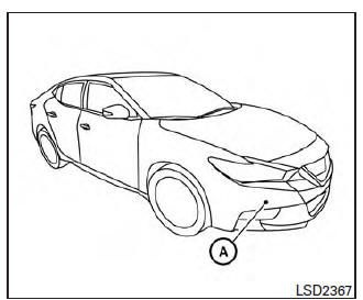
The sensor A is located behind the lower grille of the front bumper.
To keep the system operating properly, be sure to observe the following:
- Always keep the sensor area of the front bumper clean.
- Do not strike or damage the areas around the sensor.
- Do not cover or attach stickers or similar objects on the front bumper near the sensor area. This could cause failure or malfunction.
- Do not attach metallic objects near the sensor area (brush guard, etc.). This could cause failure or malfunction.
- Do not alter, remove or paint the front bumper.
Before customizing or restoring the front bumper, it is recommended that you visit a NISSAN dealer.
FCC Notice
For USA
This device complies with Part 15 of the FCC Rules. Operation is subject to the following two conditions:
1. This device may not cause harmful interference, and
2. This device must accept any interference received, including interference that may cause undesired operation.
FCC Warning
Changes or modification not expressly approved by the party responsible for compliance could void the user's authority to operate the equipment.
For Canada
This device complies with Industry Canada licence-exempt RSS standard(s). Operation is subject to the following two conditions: 1. This device may not cause interference, 2. This device must accept any interference, including interference that may cause undesired operation of the device.
 System malfunction
If the FEB system malfunctions, it will be turned
off automatically, a chime will sound, the FEB
warning light (orange) will illuminate and the
warning message [Malfunction] will appear in the
veh ...
 Predictive Forward Collision Warning (PFCW) (if so equipped)
WARNING
Failure to follow the warnings and instructions
for proper use of the PFCW system
could result in serious injury or death.
The PFCW system can help warn the
driver before a collision ...
Other materials:
Vertical synchronizing (VP) signal circuit
Description
In composite image (AUX image, camera image), transmit the vertical
synchronizing (VP) signal and horizontal
synchronizing (HP) signal from display unit to AV control unit so as to
synchronize the RGB images displayed
with AV control unit, such as the image quality adjusting men ...
P0182, P0183 FTT sensor
Description
The fuel tank temperature sensor is used to detect the fuel temperature
inside the fuel tank. The sensor modifies a voltage signal from
the ECM. The modified signal returns to the ECM as the fuel temperature
input. The sensor uses a thermistor which is sensitive to the
chang ...
Rear combination lamp
Exploded View
Slide clip
Grommets
Rear combination lamp
Removal and Installation
REAR COMBINATION LAMP
Removal
Remove the trunk side finisher. Refer to INT-36, "Removal and
Installation".
Remove the rear combination lamp nuts.
Pull the rear combination lamp toward th ...
Nissan Maxima Owners Manual
- Illustrated table of contents
- Safety-Seats, seat belts and supplemental restraint system
- Instruments and controls
- Pre-driving checks and adjustments
- Monitor, climate, audio, phone and voice recognition systems
- Starting and driving
- In case of emergency
- Appearance and care
- Do-it-yourself
- Maintenance and schedules
- Technical and consumer information
Nissan Maxima Service and Repair Manual

0.0061