Nissan Maxima Service and Repair Manual: Intake Manifold Collector
Removal and Installation
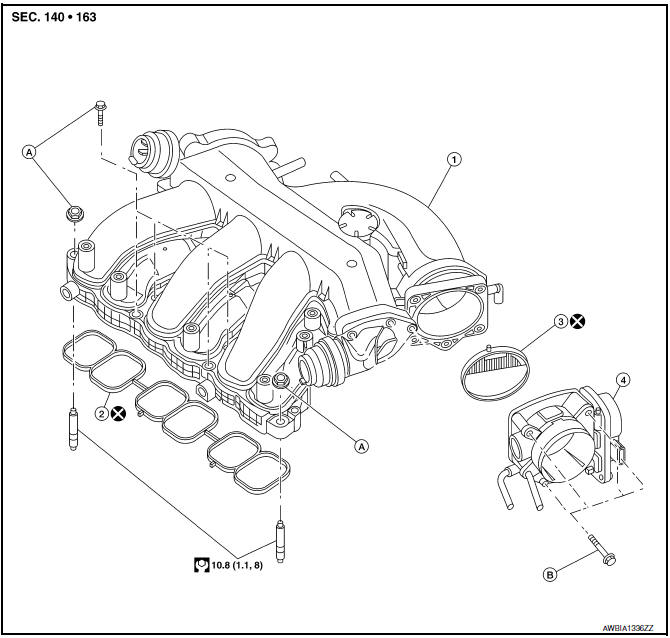
- Intake manifold collector
- Intake manifold collector gasket
- Electric throttle control actuator gasket
- Electric throttle control actuator
- Refer to INSTALLATION
- Refer to INSTALLATION
WARNING: To avoid the danger of being scalded, do not drain the coolant when the engine is hot.
CAUTION: Do not remove power valves.
NOTE: When removing components such as hoses, tubes/lines, etc., cap or plug openings to prevent fluid from spilling.
REMOVAL
- Remove the cowl top, lower cowl top extension and lower cowl top extension brace. Refer to EXT-21, "Removal and Installation".
- Remove the engine room cover. Refer to EM-23, "Removal and Installation".
- Remove front air duct and air duct hose and resonator assembly. Refer to EM-24, "Removal and Installation".
- Remove the electric throttle control actuator bolts in the reverse order as shown and remove the electric throttle control actuator and position aside.
CAUTION:
- Handle carefully to avoid any shock to the electric throttle control actuator.
- Do not disassemble.
- Disconnect the following:
- Power brake booster vacuum hose
- PCV hose
- Electric throttle control actuator electrical connector
- EVAP canister purge hose
CAUTION: Cover any engine openings to avoid the entry of any foreign material.
- Remove the EVAP canister purge volume solenoid valve bracket bolt. Position the valve aside.
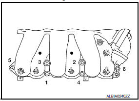
- Loosen the intake manifold collector bolts in the order as shown using power tool, and remove the intake manifold collector and gasket.
- If necessary remove the following components:
- VIAS control solenoid valve
- EVAP canister purge volume control solenoid valve
INSTALLATION
Installation is in the reverse order of removal.
CAUTION: Do not reuse intake manifold collector gasket or electric throttle control actuator gasket.
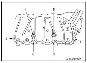
- Tighten intake manifold collector bolts in the order as shown.
- Tighten electric throttle control actuator bolts in the order shown.
NOTE: After installation, it is necessary to re-calibrate the electric throttle control actuator as follows:
- . Perform the ″Throttle Valve Closed Position Learning″ when harness connector of the electric throttle control actuator is disconnected. Refer to EC-21, "THROTTLE VALVE CLOSED POSITION LEARNING : Special Repair Requirement".
- Perform the ″Idle Air Volume Learning″ when the electric throttle control actuator is replaced. Refer to EC- 21, "IDLE AIR VOLUME LEARNING : Special Repair Requirement".
 Air Cleaner And Air Duct
Removal and Installation
Air duct hose and resonator assembly
Front air duct
Air cleaner case (lower)
Grommets
Air cleaner case mounting bracket
Bracket
Air cleaner filter
A ...
 Intake Manifold
Removal and Installation
Intake manifold
Intake manifold gaskets
Refer to INSTALLATION
REMOVAL
WARNING: To avoid the danger of being
scalded, do not drain the coolant when th ...
Other materials:
ECU diagnosis information
A/C AUTO AMP.
Reference Value
VALUES ON THE DIAGNOSIS TOOL
CONSULT MONITOR ITEM
A/C AUTO AMP. HARNESS CONNECTOR TERMINAL LAYOUT
TERMINALS AND REFERENCE VALUES FOR A/C AUTO AMP.
DTC Inspection Priority Chart
If some DTCs are displayed at the same time, perform inspections one b ...
Precaution
PRECAUTIONS
Precaution for Supplemental Restraint System (SRS) "AIR BAG" and "SEAT
BELT
PRE-TENSIONER"
The Supplemental Restraint System such as "AIR BAG" and "SEAT BELT PRE-TENSIONER",
used along
with a front seat belt, helps to reduce the risk or severity of injury to ...
Emission control information label
The emission control information label is attached
to the underside of the hood as shown.
Tire and loading information label
The cold tire pressure is shown on the Tire and
Loading Information label. The label is located as
shown.
Air conditioner specification label
The air condit ...
Nissan Maxima Owners Manual
- Illustrated table of contents
- Safety-Seats, seat belts and supplemental restraint system
- Instruments and controls
- Pre-driving checks and adjustments
- Monitor, climate, audio, phone and voice recognition systems
- Starting and driving
- In case of emergency
- Appearance and care
- Do-it-yourself
- Maintenance and schedules
- Technical and consumer information
Nissan Maxima Service and Repair Manual

0.0062