Nissan Maxima Service and Repair Manual: Air Cleaner And Air Duct
Removal and Installation
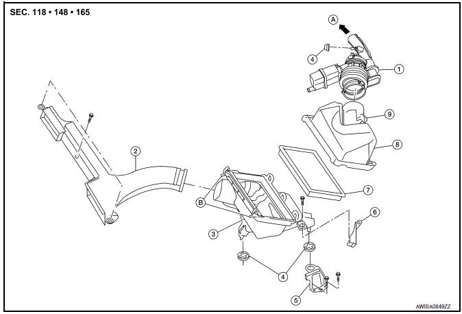
- Air duct hose and resonator assembly
- Front air duct
- Air cleaner case (lower)
- Grommets
- Air cleaner case mounting bracket
- Bracket
- Air cleaner filter
- Air cleaner case (upper)
- Mass air flow sensor
- To electric throttle control actuator
- Air cleaner case side clips
REMOVAL
- Remove engine room cover. Refer to EM-23, "Removal and Installation".
- Remove front air duct.
- Disconnect the tube clamp at the electric throttle control actuator and at the air duct hose and resonator assembly.
- Disconnect the blow-by hose.
- Remove air duct hose and resonator assembly.
- Disconnect mass air flow sensor.
- Remove mass air flow sensor from air cleaner case (upper), as necessary.
CAUTION: Handle mass air flow sensor with care.
- Do not shock it.
- Do not disassemble it.
- Do not touch its sensor.
- Disconnect transaxle breather.
- Remove air cleaner case assembly.
INSTALLATION
Installation is in the reverse order of removal.
 Engine Room Cover
Removal and Installation
CAUTION: Do not damage or scratch engine
room cover when installing or removing.
REMOVAL
Remove the engine room cover bolts and engine room cover.
INSTALLATION
I ...
 Intake Manifold Collector
Removal and Installation
Intake manifold collector
Intake manifold collector gasket
Electric throttle control actuator gasket
Electric throttle control actuator
Refer to INSTALLATION ...
Other materials:
Replacing
Replace the wiper blades if they are worn.
To replace the windshield wiper blades, follow
the procedure below:
1. Lift the wiper arm away from the windshield.
2. Push the release tab B .
3. Move the wiper blade A down and remove.
4. Insert the new wiper blade onto the wiper
arm unti ...
P0730 incorrect gear ratio
Description
TCM selects the gear ratio using the engine load (throttle position), the
primary pulley revolution speed, and
the secondary pulley revolution speed as input signals. Then it changes the
operating pressure of the primary
pulley and the secondary pulley and changes the groove wid ...
B terminal circuit
Description
"B" terminal circuit supplies power to charge the battery and operate the
vehicle's electrical system.
Diagnosis Procedure
1.CHECK "B" TERMINAL CONNECTION
Turn ignition switch OFF.
Check if "B" terminal is clean and tight
2.CHECK "B" TERMINAL CIRCUIT
Check voltage between ...
Nissan Maxima Owners Manual
- Illustrated table of contents
- Safety-Seats, seat belts and supplemental restraint system
- Instruments and controls
- Pre-driving checks and adjustments
- Monitor, climate, audio, phone and voice recognition systems
- Starting and driving
- In case of emergency
- Appearance and care
- Do-it-yourself
- Maintenance and schedules
- Technical and consumer information
Nissan Maxima Service and Repair Manual

0.0073