Nissan Maxima Service and Repair Manual: AV control unit
Removal and Installation
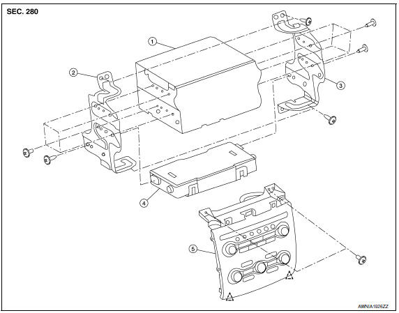
- AV control unit
- AV control unit bracket LH
- AV control unit bracket RH
- A/C auto amp.
- Cluster lid C (with A/C and AV switch assembly attached)
Clip
AV CONTROL UNIT
Removal
CAUTION: Before replacing AV control unit, perform "READ CONFIGURATION" to save current vehicle specification.
Refer to AV-180, "ADDITIONAL SERVICE WHEN REPLACING CONTROL UNIT : Special Repair Requirement".
- Disconnect the battery negative terminal.
- Remove the cluster lid D. Refer to IP-11, "Removal and Installation".
- Remove the cluster lid C
- Remove the av control unit screws (A), then pull out the av control unit (1), disconnect the av control unit connectors and remove the av control unit (1).
Installation
Installation is in the reverse order of removal.
CAUTION:
- - When replacing AV control unit, perform "WRITE CONFIGURATION". Refer to AV-180, "ADDITIONAL SERVICE WHEN REPLACING CONTROL UNIT : Special Repair Requirement".
A/C AND AV SWITCH ASSEMBLY
Removal
- Remove the cluster lid D. Refer to IP-11, "Removal and Installation".
- Remove the cluster lid C. Refer to IP-10, "Exploded View".
- Remove the A/C and AV switch assembly screws (A), then pull out the A/C and AV switch assembly (1) from cluster lid C.
Installation
Installation is in the reverse order of removal.

 Multifunction switch
Removal and Installation
REMOVAL
Remove cluster lid D. Refer to IP-10, "Exploded View".
Remove the four multifunction switch screws (A) and remove the
multifunction switch (2) from ...
Other materials:
Instrument Panel
Vent
Headlight/fog light/turn signal switch
Supplemental front-impact air bag. Horn
Meters and gauges. Warning and indicator lights. Vehicle information
display
Paddle shifters (if so equipped)
Wiper and washer switch
Audio controls*. Navigation controls*
Hazard warning flash ...
Power supply and ground circuit
A/C AUTO AMP.
A/C AUTO AMP.: Description
COMPONENT DESCRIPTION
A/C Auto Amp. (Air Conditioner Automatic Amplifier)
The A/C auto amp. (1) has a built-in microcomputer that processes
information sent from various sensors needed for air conditioner
operation. The air mix door motor(s), the mode d ...
B1023 passenger air bag off indicator
Description
DTC B1023 FRONT PASSENGER AIR BAG OFF INDICATOR
The front passenger air bag off indicator is wired to the air bag diagnosis
sensor unit. The air bag diagnosissensor unit monitors the front passenger
air bag off indicator and circuit for failures.
PART LOCATION
DTC Logic
DTC DETE ...
Nissan Maxima Owners Manual
- Illustrated table of contents
- Safety-Seats, seat belts and supplemental restraint system
- Instruments and controls
- Pre-driving checks and adjustments
- Monitor, climate, audio, phone and voice recognition systems
- Starting and driving
- In case of emergency
- Appearance and care
- Do-it-yourself
- Maintenance and schedules
- Technical and consumer information
Nissan Maxima Service and Repair Manual

0.0065