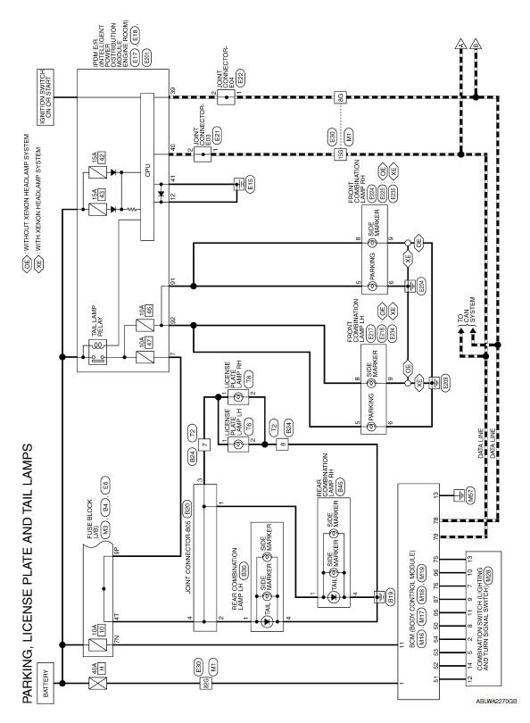
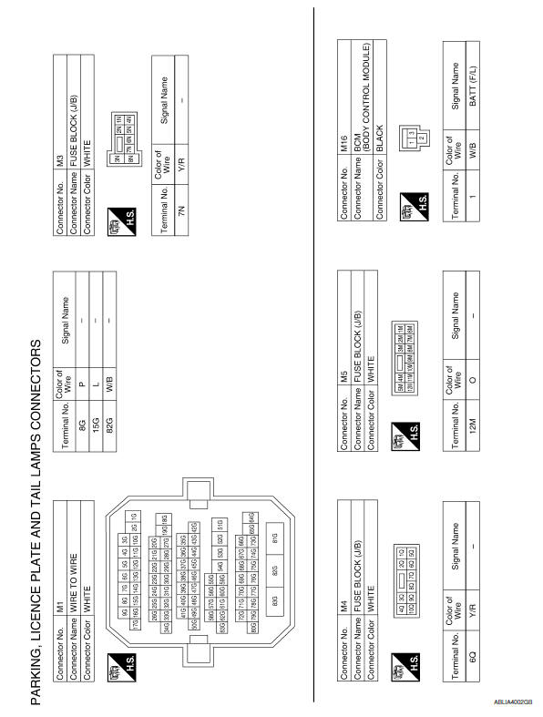
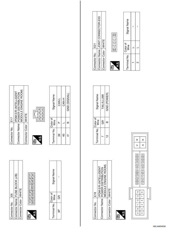
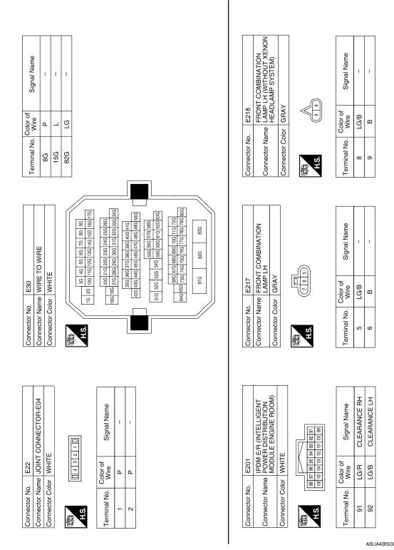
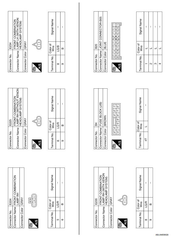
Nissan Maxima Service and Repair Manual: Parking, license plate and tail lamps system
Wiring Diagram
 Turn signal and hazard warning lamp system
Wiring Diagram
...
 Stop lamp
Wiring Diagram
...
Other materials:
P0037, P0038, P0057, P0058 HO2S2 heater
Description
SYSTEM DESCRIPTION
The ECM performs ON/OFF control of the heated oxygen sensor 2 heater
corresponding to the engine speed,
amount of intake air and engine coolant temperature.
OPERATION
DTC Logic
DTC DETECTION LOGIC
DTC CONFIRMATION PROCEDURE
1.PRECONDITIONING
If DT ...
Intelligent key system
Wiring Diagram
...
Door lock
FRONT DOOR LOCK
FRONT DOOR LOCK : Exploded View
Door key cylinder outside handle escutcheon
assembly (drivers side)
Outside handle escutcheon (passenger side)
Rear gasket
Striker
Door key cylinder rod (driver side)
Front door lock assembly
Inside handle
Outside handle b ...
Nissan Maxima Owners Manual
- Illustrated table of contents
- Safety-Seats, seat belts and supplemental restraint system
- Instruments and controls
- Pre-driving checks and adjustments
- Monitor, climate, audio, phone and voice recognition systems
- Starting and driving
- In case of emergency
- Appearance and care
- Do-it-yourself
- Maintenance and schedules
- Technical and consumer information
Nissan Maxima Service and Repair Manual

0.0069