Nissan Maxima Service and Repair Manual: Door lock
FRONT DOOR LOCK
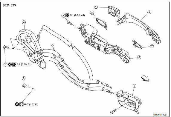
FRONT DOOR LOCK : Exploded View
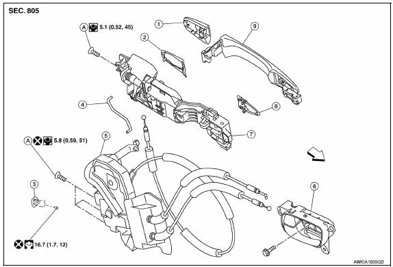
- Door key cylinder outside handle escutcheon assembly (drivers side) Outside handle escutcheon (passenger side)
- Rear gasket
- Striker
- Door key cylinder rod (driver side)
- Front door lock assembly
- Inside handle
- Outside handle bracket
- Front gasket
- Outside handle
- Bolt
Front
FRONT DOOR LOCK : Removal and Installation
REMOVAL
- Remove front door finisher. Refer to INT-18, "Removal and Installation".
- Remove front door module assembly. Refer to INT-18, "Removal and Installation".
- Disconnect door antenna and door request switch connector and remove harness clamp on outside handle bracket.
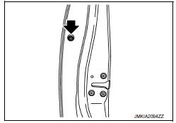
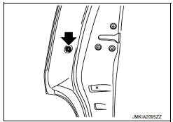
- Remove door side grommet, and loosen bolt from grommet hole.
- Disconnect the door key cylinder rod from the door key cylinder.
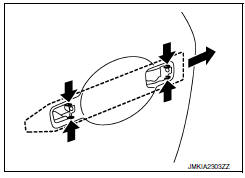
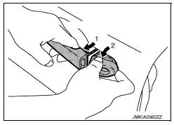
- While pulling outside handle (1), remove door key cylinder assembly (2) (driver side) or outside handle escutcheon (passenger side) (2).
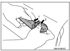
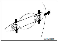
- While pulling outside handle (1), slide toward rear of vehicle (2) to remove outside handle.
- Remove front gasket and rear gasket.
- While pulling outside handle bracket, slide toward rear of vehicle to remove outside handle bracket.
- Separate the outside handle cable connection from the outside handle bracket.
- Remove door lock assembly bolts.
- Disconnect door lock actuator connector, and then remove door lock assembly.
- Remove key rod from door lock assembly.
INSTALLATION
Installation is in the reverse order of removal.
CAUTION:
- When installing do not reuse front door lock assembly screw. Always replace screw with new ones when removed.
- When installing door key cylinder rod on the LH front door, be sure to rotate door key cylinder rod holder until a click is felt.
- Check front door lock cable is properly engaged to outside handle bracket.
- After installation, check front door open/close, lock/unlock operation.
REAR DOOR LOCK
REAR DOOR LOCK : Exploded View
- Outside handle escutcheon
- Rear gasket
- Striker
- Rear door lock assembly
- Inside handle
- Outside handle bracket
- Front gasket
- Outside handle
- Bolt
 Front
Front
REAR DOOR LOCK : Removal and Installation
REMOVAL
- Remove rear door finisher. Refer to INT-21, "Removal and Installation".
- Remove sealing screen.
- Fully close the rear door glass.
- Remove door side grommet, and loosen bolt from grommet hole.
- While pulling outside handle (1), remove outside handle escutcheon (2).
- While pulling outside handle (1), slide toward rear of vehicle (2) to remove outside handle.
- Remove front gasket and rear gasket.
- While pulling outside handle bracket, slide toward rear of vehicle to remove outside handle bracket.
- Separate the outside handle cable connection from the outside handle bracket.
- Remove door lock bolts.
- Remove door lock assembly.
INSTALLATION
Installation in the reverse order of removal.
CAUTION:
- When installing do not reuse rear door lock assembly screw. Always replace screw with new ones when removed.
- Check rear door lock cable is properly engaged to outside handle bracket.
- After installation, check rear door open/close, lock/unlock operation.
 Door
Door
FRONT DOOR
FRONT DOOR : Exploded View
Front door panel
Front door check link
Front door lower hinge
Front lower hinge
Grease
FRONT DOOR : Removal and Installation
CAUTION: ...
 Trunk lid
TRUNK LID ASSEMBLY
TRUNK LID ASSEMBLY : Removal and Installation
CAUTION:
Use two people when removing or installing trunk lid assembly
due to its heavy weight.
Use protective tape or s ...
Other materials:
Main line between HVAC and A-bag circuit
Diagnosis Procedure
1.CHECK HARNESS CONTINUITY (OPEN CIRCUIT)
Turn the ignition switch OFF.
Disconnect the battery cable from the negative terminal.
Disconnect the following harness connectors.
A/C auto amp.
Harness connectors M1 and E30
Check the continuity between the A/C au ...
Windshield-washer fluid
Windshield-washer fluid reservoir
Fill the windshield-washer fluid reservoir periodically.
Add windshield-washer fluid when the low
windshield-washer fluid warning light comes on.
To fill the windshield-washer fluid reservoir, lift
the cap off the reservoir and pour the windshieldwasher ...
P1615 diffrence of key
Description
Performs ID verification through BCM and Intelligent Key
when push-button ignition switch is pressed.
Prohibits the start of engine when an unregistered ID of Intelligent Key is
used.
DTC Logic
DTC DETECTION LOGIC
DTC CONFIRMATION PROCEDURE
1.PERFORM DTC CONFIRMATION PROCED ...
Nissan Maxima Owners Manual
- Illustrated table of contents
- Safety-Seats, seat belts and supplemental restraint system
- Instruments and controls
- Pre-driving checks and adjustments
- Monitor, climate, audio, phone and voice recognition systems
- Starting and driving
- In case of emergency
- Appearance and care
- Do-it-yourself
- Maintenance and schedules
- Technical and consumer information
Nissan Maxima Service and Repair Manual

0.0063