Nissan Maxima Service and Repair Manual: Power supply and ground circuit
BCM (BODY CONTROL MODULE)
BCM (BODY CONTROL MODULE) : Diagnosis Procedure
1. CHECK FUSE AND FUSIBLE LINK
Check if the following BCM fuses or fusible link are blown.
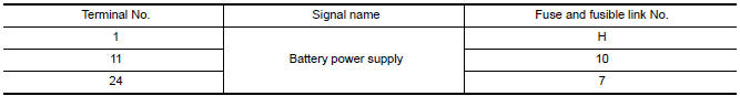
2. CHECK POWER SUPPLY CIRCUIT
- Turn ignition switch OFF.
- Disconnect BCM.
- Check voltage between BCM harness connector and ground.
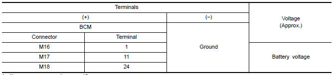
3. CHECK GROUND CIRCUIT
Check continuity between BCM harness connector and ground.

BCM (BODY CONTROL MODULE) : Special Repair Requirement
1. REQUIRED WORK WHEN REPLACING BCM
IPDM E/R (INTELLIGENT POWER DISTRIBUTION MODULE ENGINE ROOM)
IPDM E/R (INTELLIGENT POWER DISTRIBUTION MODULE ENGINE ROOM) : Diagnosis Procedure
1. CHECK FUSES AND FUSIBLE LINK
Check that the following IPDM E/R fuses or fusible link are not blown.
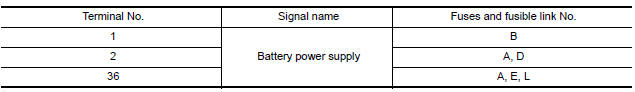
2. CHECK POWER SUPPLY CIRCUIT
- Turn ignition switch OFF.
- Disconnect IPDM E/R connectors.
- Check voltage between IPDM E/R harness connector and ground.
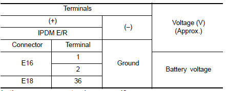
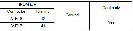
3. CHECK GROUND CIRCUIT
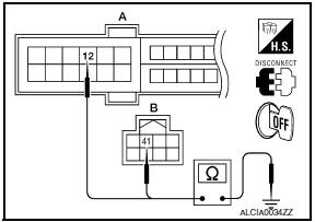
Check continuity between IPDM E/R harness connectors and ground.

 Headlamp (HI) circuit
Description
The IPDM E/R (intelligent power distribution module engine room) controls the
headlamp high relay based on inputs from the BCM over the CAN communication
lines. When the headlamp high ...
Other materials:
Hazard switch
Exploded View
Hazard switch
Cluster lid D
Removal and Installation
REMOVAL
Remove cluster lid D. Refer to IP-18, "Removal and Installation".
Disconnect the harness connector from the hazard switch.
Remove the hazard switch.
INSTALLATION
Installation is in the reverse order o ...
Lifting motor (front)
Description
The lifting motor (front) is installed to the seat frame.
The lifting motor (front) is activated with the driver seat
control unit.
The lifter (front) is moved upward/downward by changing the rotation
direction of lifting motor (front).
Component Function Check
1. CHECK ...
System maintenance
The sensor for the ICC system A is located on
the front of the vehicle.
To keep the ICC system operating properly, be
sure to observe the following:
Always keep the sensor area clean.
Do not strike or damage the areas around
the sensor. Do not touch or remove the
screw located on ...
Nissan Maxima Owners Manual
- Illustrated table of contents
- Safety-Seats, seat belts and supplemental restraint system
- Instruments and controls
- Pre-driving checks and adjustments
- Monitor, climate, audio, phone and voice recognition systems
- Starting and driving
- In case of emergency
- Appearance and care
- Do-it-yourself
- Maintenance and schedules
- Technical and consumer information
Nissan Maxima Service and Repair Manual

0.006