Nissan Maxima Service and Repair Manual: U1263 USB
DTC Logic
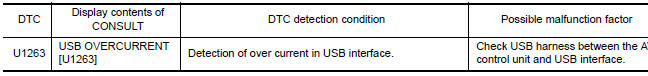
Diagnosis Procedure
1.CHECK USB HARNESS
Visually check USB harness.
 U1243 display unit
Description
Part name
Description
DISPLAY UNIT
Display image is controlled by the serial communication from AV
control unit.
Inputs the RGB i ...
 U1255 satellite radio tuner
Descriptio
Part name
Description
SATELLITE RADIO TUNER
Inputs the satellite radio signal from satellite radio antenna
and outputs the sound signa ...
Other materials:
P0453 evap control system pressure sensor
Description
The EVAP control system pressure sensor detects pressure in the
purge line. The sensor output voltage to the ECM increases as pressure
increases.
DTC Logic
DTC DETECTION LOGIC
DTC CONFIRMATION PROCEDURE
1.PRECONDITIONING
If DTC Confirmation Procedure has been previously ...
Front drive shaft
Removal and Installation (LH)
Drive shaft
Cotter pin
REMOVAL
Remove wheel and tire using power tool. Refer to WT-60, "Adjustment".
Remove wheel sensor from steering knuckle. Refer to BRC-102,
"Removal and Installation - Front Wheel Sensor".CAUTION: Do not
pull o ...
Exterior rear
Rear window defroster switch
High-mounted stop light
Interior trunk lid release. Trunk lid
Exterior trunk lid release/request button. Rearview camera
Rear sonar sensors (if so equipped)
Replacing bulbs
Fuel-filler door. Fuel recommendation
Child safety rear door locks
R ...
Nissan Maxima Owners Manual
- Illustrated table of contents
- Safety-Seats, seat belts and supplemental restraint system
- Instruments and controls
- Pre-driving checks and adjustments
- Monitor, climate, audio, phone and voice recognition systems
- Starting and driving
- In case of emergency
- Appearance and care
- Do-it-yourself
- Maintenance and schedules
- Technical and consumer information
Nissan Maxima Service and Repair Manual

0.0075