Nissan Maxima Service and Repair Manual: U1255 satellite radio tuner
Descriptio
| Part name | Description |
| SATELLITE RADIO TUNER |
|
DTC Logic
Diagnosis Procedure
1.CHECK SATELLITE RADIO TUNER POWER SUPPLY AND GROUND CIRCUIT
Check satellite radio tuner power supply and ground circuit
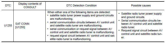
2.CHECK CONTINUITY COMMUNICATION CIRCUIT AND REQUEST SIGNAL CIRCUIT
- Turn ignition switch OFF.
- Disconnect AV control unit connector M116 and satellite radio tuner connector B111.
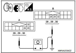
- Check continuity between AV control unit harness connector M116 (A) and satellite radio tuner harness connector B111 (B).
- Check continuity between AV control unit harness connector M116 (A) and groun
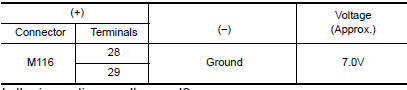
3.CHECK AV CONTROL UNIT VOLTAGE
- Connect AV control unit connector.
- Turn ignition switch ON.
- Check voltage between AV control unit harness connector M116 and ground.
4.CHECK SATELLITE RADIO TUNER
- Turn ignition switch OFF.
- Disconnect AV control unit connector.
- Connect satellite radio tuner.
- Turn ignition switch ON.
- Check voltage between satellite radio tuner harness connector terminal ground.

 U1263 USB
DTC Logic
Diagnosis Procedure
1.CHECK USB HARNESS
Visually check USB harness. ...
 U1300 AV comm circuit
Description
U1300 is indicated when a communication signal malfunction occurs. U1300 is
indicated along with DTCs that identify components connected to the AV
control unit through communication l ...
Other materials:
Subwoofer
Removal and Installation
Subwoofer LH
Subwoofer RH
Subwoofer screws
Subwoofer connectors
REMOVAL
Remove the rear parcel shelf finisher. Refer to INT-36, "Removal
and Installation".
Remove the subwoofer screws.
Pull out the subwoofer, disconnect the harness c ...
RCTA system limitations
WARNING
Listed below are the system limitations for
the RCTA system. Failure to operate the
vehicle in accordance with these system
limitations could result in serious injury or
death.
Always check surroundings and turn to
check what is behind you before backing
up. The radar sensors det ...
Automatic drive positioner system
AUTOMATIC DRIVE POSITIONER SYSTEM : System Diagram
AUTOMATIC DRIVE POSITIONER SYSTEM : System Description
OUTLINE
The system automatically moves the driver seat, steering column and door
mirror position by the driver seat control unit and the automatic drive
positioner control unit. The d ...
Nissan Maxima Owners Manual
- Illustrated table of contents
- Safety-Seats, seat belts and supplemental restraint system
- Instruments and controls
- Pre-driving checks and adjustments
- Monitor, climate, audio, phone and voice recognition systems
- Starting and driving
- In case of emergency
- Appearance and care
- Do-it-yourself
- Maintenance and schedules
- Technical and consumer information
Nissan Maxima Service and Repair Manual

0.0076