Nissan Maxima Service and Repair Manual: U1300 AV comm circuit
Description
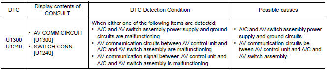
U1300 is indicated when a communication signal malfunction occurs. U1300 is indicated along with DTCs that identify components connected to the AV control unit through communication lines. Determine the possible malfunction cause from the table below.
SELF-DIAGNOSIS RESULTS DISPLAY ITEM
 U1255 satellite radio tuner
Descriptio
Part name
Description
SATELLITE RADIO TUNER
Inputs the satellite radio signal from satellite radio antenna
and outputs the sound signa ...
 U1310 AV control unit
Description
Part name
Description
AV CONTROL UNIT
It is the master unit of the MULTI AV system and it is connected
to each control unit by means ...
Other materials:
Rear door speaker
Removal and Installation
REMOVAL
Remove the rear door finisher. Refer to INT-21, "Removal and
Installation".
Remove the rear door speaker screws (A).
Disconnect the harness connector (B) from the rear door speaker
(1) and remove.
INSTALLATION
Installation is in the reverse order ...
Diagnosis and repair work flow
Work Flow
OVERALL SEQUENCE
DETAILED FLOW
1.GET INFORMATION FOR SYMPTOM
Get the detailed information from the customer about the symptom
(the condition and the environment
when the incident/malfunction occurred) using the "Diagnostic Work Sheet".
(Refer to EC-12, "Diagnostic ...
B210b starter control relay
DTC Logic
DTC DETECTION LOGIC
NOTE:
If DTC B210B is displayed with DTC
U1000, first perform the trouble diagnosis for DTC U1000. Refer to
SEC-29, "DTC Logic".
If DTC B210B is displayed with DTC
U1010, first perform the trouble diagnosis for DTC U1010. Refer to
SEC-30, "D ...
Nissan Maxima Owners Manual
- Illustrated table of contents
- Safety-Seats, seat belts and supplemental restraint system
- Instruments and controls
- Pre-driving checks and adjustments
- Monitor, climate, audio, phone and voice recognition systems
- Starting and driving
- In case of emergency
- Appearance and care
- Do-it-yourself
- Maintenance and schedules
- Technical and consumer information
Nissan Maxima Service and Repair Manual

0.0084