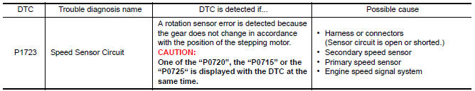
Nissan Maxima Service and Repair Manual: P1723 speed sensor
Description
The secondary speed sensor detects the revolution of parking gear and generates a pulse signal. The pulse signal is sent to the TCM, which converts it into vehicle speed.
The primary speed sensor detects the primary pulley revolution speed and sends a signal to the TCM.
DTC Logic
DTC DETECTION LOGIC
DTC CONFIRMATION PROCEDURE
CAUTION: Always drive vehicle at a safe speed.
NOTE: Immediately after performing any "DTC CONFIRMATION PROCEDURE", always turn ignition switch OFF.
Then wait at least 10 seconds before performing the next test.
1.CHECK DTC DETECTION
 With CONSULT
-
Turn ignition switch ON.
-
Select "Data Monitor" in "TRANSMISSION".
-
Start engine and maintain the following conditions for at least 5 consecutive seconds.
VEHICLE SPEED : 10 km/h (6 MPH) or more
ACC PEDAL OPEN : More than 1.0/8
RANGE : "D" position
ENG SPEED : 450 rpm or more
Driving location : Driving the vehicle uphill (increased engine load) will help maintain the driving conditions required for this test.
Diagnosis Procedure
1.CHECK STEP MOTOR FUNCTION
Perform "Self Diagnostic Results" in "TRANSMISSION".
2.CHECK SECONDARY SPEED SENSOR SYSTEM
Check secondary speed sensor system. Refer to TM-60, "DTC Logic".
3.CHECK PRIMARY SPEED SENSOR SYSTEM
Check primary speed sensor system. Refer to TM-57, "DTC Logic".
4.CHECK ENGINE SPEED SIGNAL SYSTEM
Check engine speed signal system. Refer to TM-64, "DTC Logic".
5.DETECT MALFUNCTIONING ITEMS
Check TCM connector pin terminals for damage or loose connection with harness connector.
 P1722 vehicle speed
Description
The vehicle speed signal is transmitted from ABS actuator
and electric unit (control unit) to TCM via CAN communication
line.
DTC Logic
DTC DETECTION LOGIC
DTC CONFIRMATION PROCE ...
 P1726 throttle control signal
Description
The electric throttle control actuator consists of
throttle control motor, accelerator pedal position sensor, throttle
position sensor, etc. The actuator sends a signal to the ECM, an ...
Other materials:
ABS branch line circuit
Diagnosis Procedure
1.CHECK CONNECTOR
Turn the ignition switch OFF.
Disconnect the battery cable from the negative terminal.
Check the terminals and connectors of the ABS actuator and
electric unit (control unit) for damage, bend
and loose connection (unit side and connector side).
...
P2119 electric throttle control actuator
Description
Electric throttle control actuator consists of throttle control motor,
throttle position sensor, etc.
The throttle control motor is operated by the ECM and it opens and closes the
throttle valve.
The throttle position sensor detects the throttle valve position, and the
openi ...
MOD system limitations
WARNING
Listed below are the system limitations for
MOD. Failure to operate the vehicle in
accordance with these system limitations
could result in serious injury or death.
Do not use the MOD system when towing
a trailer. The system may not function
properly.
Excessive noise (for examp ...
Nissan Maxima Owners Manual
- Illustrated table of contents
- Safety-Seats, seat belts and supplemental restraint system
- Instruments and controls
- Pre-driving checks and adjustments
- Monitor, climate, audio, phone and voice recognition systems
- Starting and driving
- In case of emergency
- Appearance and care
- Do-it-yourself
- Maintenance and schedules
- Technical and consumer information
Nissan Maxima Service and Repair Manual

0.0066