Nissan Maxima Service and Repair Manual: System description
EPS SYSTEM
System Diagram
CONTROL DIAGRAM
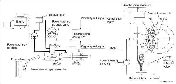
System Description
- The EPS system controls the power steering solenoid valve
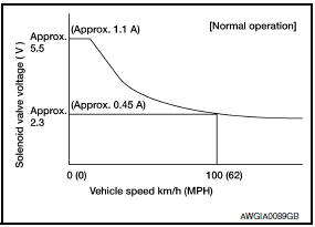
through the power steering control unit. - The valve driving voltage to control the power steering solenoid
valve varies according to the vehicle speed.
OPERATION PRINCIPLE
During Parking (When Turning The Steering Wheel To The Right)
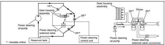
- Power steering solenoid valve is closed while a vehicle is stopped.
- Pinion "1R", "2R" and "3R" are closed depending on steering torque of steering wheel.
- Oil pressure "P" in the gear housing assembly is the sum of oil
pressures occurring in "2R" and "3R". This
results in a light steering force because of high pressure.
During High-speed Operation
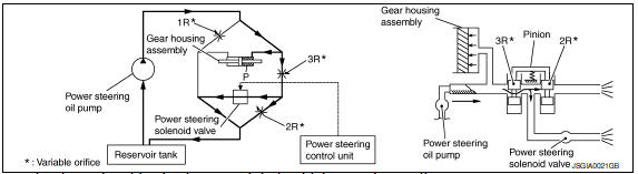
- Power steering solenoid valve is opened during high-speed operation.
- Pinion "1R", "2R" and "3R" are closed depending on steering torque of steering wheel.
- Oil pressure "2R" does not occur because the power steering solenoid valve is on full throttle.
- Oil pressure "P" in the gear housing assembly includes only oil pressure
occurring in "3R" and results in a
heavy steering force.
Component Parts Location
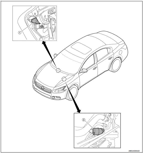
- Power steering control unit M59
(view with glove box removed) - Power steering solenoid valve E14
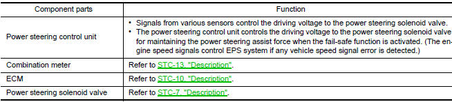
Component Description
 Basic inspection
DIAGNOSIS AND REPAIR WORKFLOW
Work Flow
DETAILED FLOW
1.COLLECT THE INFORMATION FROM THE CUSTOMER
It is also important to clarify customer complaints before inspection. First
of all, reproduce s ...

Other materials:
Tire Pressure Monitoring System (TPMS)
This vehicle is equipped with the TPMS. It monitors
tire pressure of all tires except the spare.
When the low tire pressure warning light is lit and
the "Tire Pressure Low-Add Air" warning appears
in the vehicle information display, one or more of
your tires is significantly under-inflated. I ...
Additional service when replacing control unit (bcm)
ADDITIONAL SERVICE WHEN REPLACING CONTROL UNIT (BCM) : Description
BEFORE REPLACEMENT
When replacing BCM, save or print current vehicle specification with CONSULT
configuration before replacement.
NOTE:
If "Before Replace ECU" cannot be used, use the "After Replace ECU" or ...
Rear door glass
Exploded View
Door glass run
Door panel
Window motor
Regulator assembly
Partition glass run
Partition glass
Partition sash
Door glass
Removal and Installation
REMOVAL
Remove the rear door finisher. Refer to INT-21, "Removal and
Installation".
Position the vap ...
Nissan Maxima Owners Manual
- Illustrated table of contents
- Safety-Seats, seat belts and supplemental restraint system
- Instruments and controls
- Pre-driving checks and adjustments
- Monitor, climate, audio, phone and voice recognition systems
- Starting and driving
- In case of emergency
- Appearance and care
- Do-it-yourself
- Maintenance and schedules
- Technical and consumer information
Nissan Maxima Service and Repair Manual

0.0059