Nissan Maxima Service and Repair Manual: U1263 USB
DTC Logic
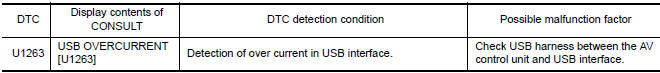
Diagnosis Procedure
1.CHECK USB HARNESS
Visually check USB harness.
 U1244 GPS antenna
DTC Logic
Diagnosis Procedure
1.GPS ANTENNA CHECK
Inspect GPS antenna and antenna feeder for damage or poor connection.
2.CHECK AV CONTROL UNIT VOLTAGE
Turn ignition switch ON.
Check ...
 U1300 AV comm circuit
Description
U1300 is indicated when malfunction occurs in communication signal of multi
AV system. Indicated simultaneously,
without fail, with the malfunction of control units connected to AV co ...
Other materials:
Evaporative emission system
System Diagram
System Description
*1: ECM determines the start signal status by the signals of engine speed and
battery voltage.
*2: This signal is sent to the ECM via the CAN communication line.
SYSTEM DESCRIPTION
The evaporative emission system is used to reduce hydrocarbons emitte ...
Entry assist function
ENTRY ASSIST FUNCTION : System Diagram
ENTRY ASSIST FUNCTION : System Description
OUTLINE
The seat is in the exiting position when either following condition is
satisfied, the seat returns from exiting position to the previous driving
position.
NOTE:
This function is set to OFF befor ...
Headlining
Exploded View
Rear assist grip
Front assist grip
Front room/map lamp assembly (dual panel- sunroof)
Sun visor (RH)
Sun visor (LH)
Mirror harness cover
Sun visor cover
Front room/map lamp assembly
Sun visor holder
Rear assist grip LH
Headlining assembly (single panel s ...
Nissan Maxima Owners Manual
- Illustrated table of contents
- Safety-Seats, seat belts and supplemental restraint system
- Instruments and controls
- Pre-driving checks and adjustments
- Monitor, climate, audio, phone and voice recognition systems
- Starting and driving
- In case of emergency
- Appearance and care
- Do-it-yourself
- Maintenance and schedules
- Technical and consumer information
Nissan Maxima Service and Repair Manual

0.0056