Nissan Maxima Service and Repair Manual: Main line between A-bag and ABS circuit
Diagnosis Procedure
1.CHECK CONNECTOR
- Turn the ignition switch OFF.
- Disconnect the battery cable from the negative terminal.
- Check the following terminals and connectors for damage, bend and
loose connection (connector side
and harness side).
- Harness connector M1
- Harness connector E30
2.CHECK HARNESS CONTINUITY (OPEN CIRCUIT)
- Disconnect the following harness connectors.
- A/C auto amp.
- Harness connectors M1 and E30
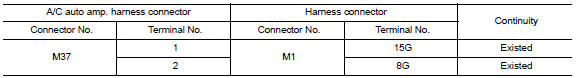
- Check the continuity between the A/C auto amp. harness connector and the harness connector.
3.CHECK HARNESS CONTINUITY (OPEN CIRCUIT)
- Disconnect the connector of ABS actuator and electric unit (control unit).
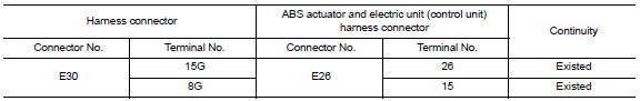
- Check the continuity between the harness connector and the ABS actuator and electric unit (control unit) harness connector.
 Main line between HVAC and A-bag circuit
Diagnosis Procedure
1.CHECK HARNESS CONTINUITY (OPEN CIRCUIT)
Turn the ignition switch OFF.
Disconnect the battery cable from the negative terminal.
Disconnect the following harness connector ...
 ECM branch line circuit
Diagnosis Procedure
1.CHECK CONNECTOR
Turn the ignition switch OFF.
Disconnect the battery cable from the negative terminal.
Check the following terminals and connectors for damage, bend and ...
Other materials:
Electronic controlled engine mount
Description
In the idle range, ECM turns OFF the electronically-controlled engine mount
control solenoid valve and applies
manifold pressure to the electronically controlled engine mount. This decreases
damping force of the electronically-
controlled engine mount and absorbs vibrations trav ...
Automatic drive positioner control unit
Reference Value
TERMINAL LAYOUT
PHYSICAL VALUES
...
Installing the spare tire
The spare tire is designed for emergency
use. For additional information, refer to
"Wheels and tires" in the "Do-it-yourself"
section of this manual.
1. Clean any mud or dirt from the surface between
the wheel and hub.
2. Carefully put the spare tire on and tighten
the wheel nuts finger ...
Nissan Maxima Owners Manual
- Illustrated table of contents
- Safety-Seats, seat belts and supplemental restraint system
- Instruments and controls
- Pre-driving checks and adjustments
- Monitor, climate, audio, phone and voice recognition systems
- Starting and driving
- In case of emergency
- Appearance and care
- Do-it-yourself
- Maintenance and schedules
- Technical and consumer information
Nissan Maxima Service and Repair Manual

0.0066