Nissan Maxima Service and Repair Manual: Power supply and ground circuit
A/C AUTO AMP.
A/C AUTO AMP.: Description
COMPONENT DESCRIPTION
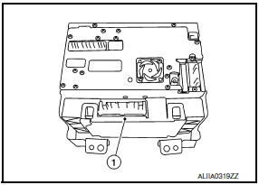
A/C Auto Amp. (Air Conditioner Automatic Amplifier) The A/C auto amp. (1) has a built-in microcomputer that processes information sent from various sensors needed for air conditioner operation. The air mix door motor(s), the mode door motor, the intake door motor, the blower motor and the compressor are then controlled.
When the various switches and temperature control dial are operated, data is input to the A/C auto amp. from the AV control unit using CAN communication.
The A/C auto amp. is operated with control mechanisms. Signals from various switches and Potentio Temperature Control (PTC) are directly entered into the A/C auto amp.
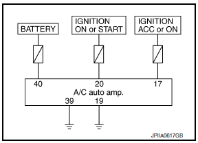
Power Supply and Ground Circuit for A/C Auto Amp.
A/C AUTO AMP.: Component Function Check
1.CHECK OPERATION
- Press the AUTO switch, and then check that "AUTO" is shown on the display.
- Operate the temperature control dial (driver side). Check that the fan speed or outlet changes. (The discharge air temperature or fan speed varies depending on the ambient temperature, in-vehicle temperature, and temperature setting.)
A/C AUTO AMP.: Diagnosis Procedure
1.CHECK FOR AUDIO DTCS WITH CONSULT
Using CONSULT, perform "SELF-DIAGNOSIS RESULTS" of MULTI AV.
2.CHECK A/C AUTO AMP. POWER SUPPLY
- Turn ignition switch OFF.
- Disconnect the A/C auto amp. connector.
- Turn ignition switch ON.
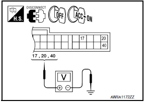
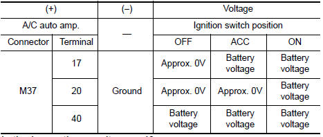
- Check voltage between A/C auto amp. harness connector M37 terminal 17, 20, 40 and ground.
3.CHECK FUSE
Check 10A fuses [Nos. 3, 6 and 17, located in the fuse block (J/B)].
4.CHECK A/C AUTO AMP. GROUND CIRCUIT
- Turn ignition switch OFF.
- Check continuity between A/C auto amp. harness connector M37 terminals 19, 39 and ground.
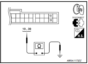
19, 39 - Ground: Continuity should exist.
A/C AND AV SWITCH ASSEMBLY
A/C AND AV SWITCH ASSEMBLY: Component Function Check
1.CHECK OPERATION
- Press the AUTO switch, and then check that "AUTO" is shown on the display.
- Operate the temperature control dial (driver side). Check that the fan speed or outlet changes. (The discharge air temperature or fan speed varies depending on the ambient temperature, in-vehicle temperature, and temperature setting.)
A/C AND AV SWITCH ASSEMBLY: Diagnosis Procedure
1.CHECK FOR AUDIO DTCS WITH CONSULT
Using CONSULT, perform "SELF-DIAGNOSIS RESULTS" of MULTI AV.
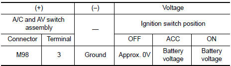
2.CHECK A/C AND AV SWITCH ASSEMBLY POWER SUPPLY
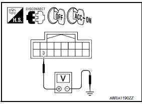
- Disconnect the A/C and AV switch assembly connector.
- Check voltage between A/C and AV switch assembly harness connector M98 terminal 3 and ground.
3.CHECK FUSE
Check 10A fuse [No.17, located in the fuse block (J/B)].
4.CHECK A/C AND AV SWITCH ASSEMBLY GROUND CIRCUIT
- Turn ignition switch OFF.
- Check continuity between A/C and AV switch assembly harness connector M98 terminal 1 and ground.
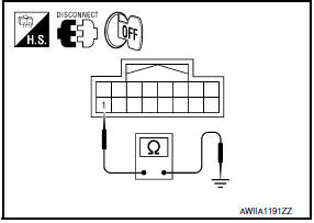
1 - Ground: Continuity should exist.
 Magnet clutch
Description
SYSTEM DESCRIPTION
A/C auto amp. controls A/C compressor operation by ambient temperature and
signal from ECM.
Low Temperature Protection Control
A/C auto amp. will turn the A/ ...
 ECU diagnosis information
A/C AUTO AMP
Reference Value
VALUES ON THE DIAGNOSIS TOOL
CONSULT MONITOR ITEM
A/C AUTO AMP. HARNESS CONNECTOR TERMINAL LAYOUT
TERMINALS AND REFERENCE VALUES FOR A/C AUTO AMP.
Fa ...
Other materials:
Hydraulic line
Exploded View
High pressure hose
Suction hose
Reservoir tank bracket
Reservoir tank
Oil pump assembly
Steering gear assembly
Low pressure piping
Eye bolt
High pressure piping
Copper sealing washers
Eye bolt
Copper sealing washers
Power steering pressure sensor
...
Driving on snow or ice
WARNING
Wet ice (32F, 0C and freezing rain),
very cold snow or ice can be slick and
very hard to drive on. The vehicle will
have much less traction or "grip" under
these conditions. Try to avoid driving on
wet ice until the road is salted or
sanded.
Whatever the condition, drive wi ...
Automatic anti-glare rearview mirror
The inside mirror is designed so that it automatically
dims during night time conditions and according
to the intensity of the headlights of the
vehicle following you. The automatic anti-glare
feature is activated when the ignition switch is in
the ON position.
The indicator light will i ...
Nissan Maxima Owners Manual
- Illustrated table of contents
- Safety-Seats, seat belts and supplemental restraint system
- Instruments and controls
- Pre-driving checks and adjustments
- Monitor, climate, audio, phone and voice recognition systems
- Starting and driving
- In case of emergency
- Appearance and care
- Do-it-yourself
- Maintenance and schedules
- Technical and consumer information
Nissan Maxima Service and Repair Manual

0.0063