Nissan Maxima Service and Repair Manual: Power supply and ground circuit
BCM
BCM : Diagnosis Procedure
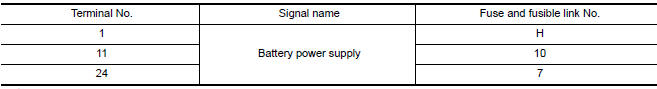
1. CHECK FUSE AND FUSIBLE LINK
Check if the following BCM fuses or fusible link are blown.
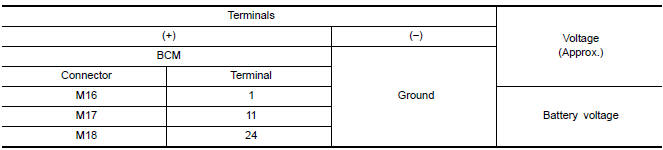
2. CHECK POWER SUPPLY CIRCUIT
- Turn ignition switch OFF.
- Disconnect BCM.
- Check voltage between BCM harness connector and ground.
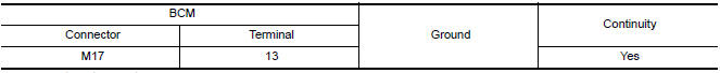
3. CHECK GROUND CIRCUIT
Check continuity between BCM harness connector and ground.
SUNROOF MOTOR ASSEMBLY
SUNROOF MOTOR ASSEMBLY : Description
- BCM supplies power.
- CPU is integrated in sunroof motor assembly.
- Tilts up/down & slides open/close by sunroof switch operation.
- In order to close sunroof lid certainly with the signal from combination meter at the time of high speed run, the sunroof motor torque at the time of tilt-down operation is controlled.
SUNROOF MOTOR ASSEMBLY : Component Function Check
1. CHECK SUNROOF MOTOR FUNCTION
Do tilt up/down & slide open/close functions operate normally with sunroof switch?
SUNROOF MOTOR ASSEMBLY : Diagnosis Procedure
SUNROOF MOTOR ASSEMBLY
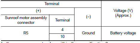
1. CHECK POWER SUPPLY CIRCUIT
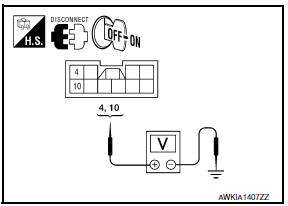
- Turn ignition switch OFF.
- Disconnect sunroof motor assembly.
- Turn ignition switch ON.
- Check voltage between sunroof motor assembly connector and ground.
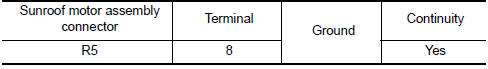
2. CHECK GROUND CIRCUIT
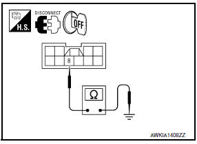
- Turn ignition switch OFF.
- Check continuity between sunroof motor assembly connector and ground.
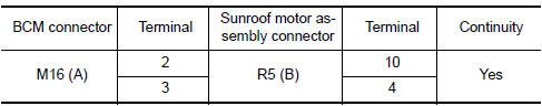
3. CHECK SUNROOF MOTOR CIRCUIT
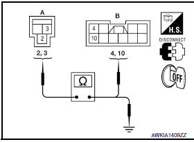
- Turn ignition switch OFF.
- Disconnect BCM.
- Check continuity between BCM connector (A) and sunroof motor assembly connector (B).
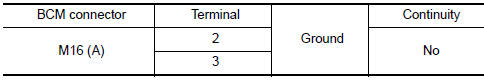
- Check continuity between BCM connector (A) and ground.
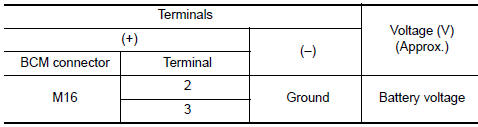
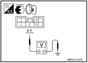
4. CHECK BCM OUTPUT SIGNAL

- Connect BCM.
- Turn ignition switch ON.
- Check voltage between BCM connector and ground.
5. CHECK SUNROOF SWITCH INPUT SIGNAL
- Connect sunroof motor assembly.
- Turn ignition switch ON.
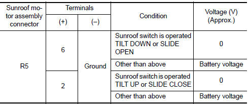
- Check voltage between sunroof motor assembly connector and ground.
6. CHECK SUNROOF SWITCH CIRCUIT
- Turn ignition switch OFF.
- Disconnect sunroof motor assembly and sunroof switch.
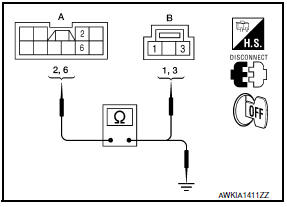
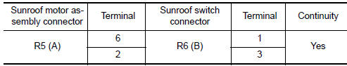
- Check continuity between sunroof motor assembly connector (A) and sunroof switch connector (B).
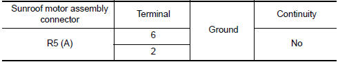
- Check continuity between sunroof motor assembly connector (A) and ground.
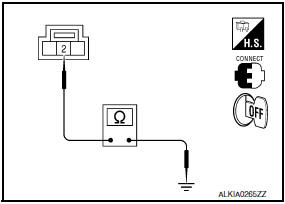
7. CHECK SUNROOF SWITCH GROUND CIRCUIT
- Connect sunroof motor assembly.
- Check continuity between sunroof switch connector and ground.
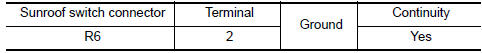
8. CHECK COMBINATION METER SIGNAL
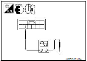
- Connect sunroof motor assembly.
- Turn ignition switch ON.
- Check signal between sunroof motor assembly connector and ground with oscilloscope.
9.CHECK COMBINATION METER CIRCUIT
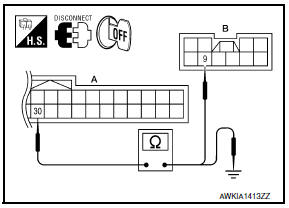
- Turn ignition switch OFF.
- Disconnect combination meter.
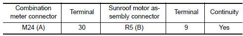
- Check continuity between combination meter connector (A) and sunroof motor assembly connector (B).
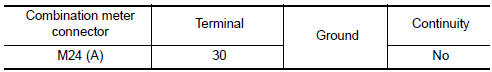
- Check continuity between combination meter connector (A) and ground.
SUNROOF MOTOR ASSEMBLY : Component Inspection
SUNROOF SWITCH
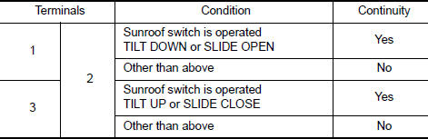
1. CHECK SUNROOF SWITCH
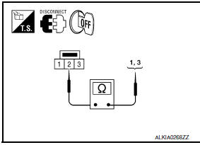
- Turn ignition switch OFF.
- Disconnect sunroof switch.
SUNROOF MOTOR ASSEMBLY : Special Repair Requirement
1. PERFORM INITIALIZATION PROCEDURE
Perform initialization procedur
2. CHECK ANTI-PINCH OPERATION
Check anti-pinch operation.

 Door switch
Description
Detects door open/close condition.
Component Function Check
1.CHECK FUNCTION
With CONSULT
Check door switches DOOR SW-DR, DOOR SW-AS in Data Monitor mode with CONSULT.
Diagnosis Pr ...
Other materials:
Symptom diagnosis
AUDIO SYSTEM
Symptom Table
AUDIO SYSTEM
Symptoms
Check items
Probable malfunction location
The disk cannot be removed.
Audio unit
Malfunction in audio unit.
Refer to AV-73, "Removal and
Installation".
No sound comes out ...
B2630, B2631 sunload sensor
Description
COMPONENT DESCRIPTION
Sunload Sensor
The sunload sensor (1) is located on the driver'side defroster
grille.
It detects sunload entering through windshield by means of a
photo diode. The sensor converts the sunload into a current value,
which is then input into the A/C auto ...
P1805 brake switch
Description
Brake switch signal is applied to the ECM via the stop lamp switch when the
brake pedal is depressed. This
signal is used mainly to decrease the engine speed when the vehicle is being
driver.
DTC Logic
DTC DETECTION LOGIC
DTC CONFIRMATION PROCEDURE
1.PERFORM DTC CONFIRMATI ...
Nissan Maxima Owners Manual
- Illustrated table of contents
- Safety-Seats, seat belts and supplemental restraint system
- Instruments and controls
- Pre-driving checks and adjustments
- Monitor, climate, audio, phone and voice recognition systems
- Starting and driving
- In case of emergency
- Appearance and care
- Do-it-yourself
- Maintenance and schedules
- Technical and consumer information
Nissan Maxima Service and Repair Manual

0.0069