
Nissan Maxima Service and Repair Manual: C1110, C1153, C1170 ABS actuator and electric unit (control unit)
DTC Logic
DTC DETECTION LOGIC

DTC CONFIRMATION PROCEDURE
1.CHECK SELF-DIAGNOSIS RESULTS
Check the self-diagnosis results.
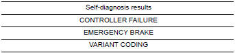
Diagnosis Procedure
1.REPLACE ABS ACTUATOR AND ELECTRIC UNIT (CONTROL UNIT)
CAUTION: Replace ABS actuator and electric unit (control unit) when self-diagnostic result shows items other than that applicable.
Special Repair Requirement
1.ADJUSTMENT OF STEERING ANGLE SENSOR NEUTRAL POSITION
Always perform the neutral position adjustment for the steering angle sensor, when replacing the ABS actuator and electric unit (control unit).
 C1109 battery voltage [abnormal]
Description
Supplies electric power to the ABS actuator and electric unit (control unit).
DTC Logic
DTC DETECTION LOGIC
DTC CONFIRMATION PROCEDURE
1.CHECK SELF-DIAGNOSIS RESULTS
Check the se ...
 C1111 pump motor
Description
PUMP
The pump returns the brake fluid stored in the reservoir to the master
cylinder by reducing the pressure.
MOTOR
The motor drives the pump according to the signals transmitted by ...
Other materials:
Insufficient cooling
Component Function Check
Symptom
Insufficient cooling
No cool air comes out. (Airflow volume is normal.)
INSPECTION FLOW
1. CONFIRM SYMPTOM BY PERFORMING OPERATION CHECK - TEMPERATURE DECREASE
Press the AUTO switch.
Turn temperature control switch (driver side) counterclockwise
u ...
U1218 AV control unit
DTC Logic
U1219 AV CONTROL UNIT
DTC Logic
U121A AV CONTROL UNIT
DTC Logic
U121B AV CONTROL UNIT
DTC Logic
U121C AV CONTROL UNIT
DTC Logic
...
Satellite radio tuner
Removal and Installation
REMOVAL
Disconnect the battery negative terminal.
Remove the trunk upper finisher. Refer to INT-36, "Exploded View".
Remove the parcel shelf finisher. Refer to INT-28, "Removal and
Installation".
From inside the passenger compartment, remove the bracket screw ...
Nissan Maxima Owners Manual
- Illustrated table of contents
- Safety-Seats, seat belts and supplemental restraint system
- Instruments and controls
- Pre-driving checks and adjustments
- Monitor, climate, audio, phone and voice recognition systems
- Starting and driving
- In case of emergency
- Appearance and care
- Do-it-yourself
- Maintenance and schedules
- Technical and consumer information
Nissan Maxima Service and Repair Manual

0.0075