Nissan Maxima Service and Repair Manual: C1109 battery voltage [abnormal]
Description
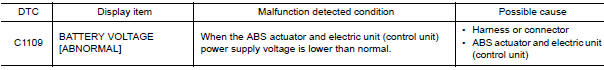
Supplies electric power to the ABS actuator and electric unit (control unit).
DTC Logic
DTC DETECTION LOGIC
DTC CONFIRMATION PROCEDURE
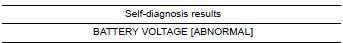
1.CHECK SELF-DIAGNOSIS RESULTS
Check the self-diagnosis results.
Diagnosis Procedure
1.CONNECTOR INSPECTION
- Turn ignition switch OFF.
- Disconnect ABS actuator and electric unit (control unit) connector.
- Check terminals for deformation, disconnection, looseness, and so on. If any malfunction is found, repair or replace terminals.
- Reconnect connector and perform self-diagnosis
2.CHECK ABS ACTUATOR AND ELECTRIC UNIT (CONTROL UNIT) POWER SUPPLY CIRCUIT AND GROUND CIRCUIT
- Turn ignition switch OFF.
- Disconnect ABS actuator and electric unit (control unit) connector.
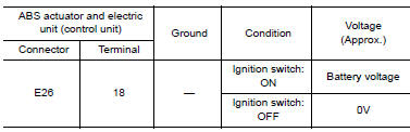
- Check voltage between ABS actuator and electric unit (control unit) connector E26 terminal 18 and ground
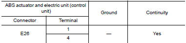
- Turn ignition switch OFF.
- Check continuity between ABS actuator and electric unit (control unit) connector E26 terminals 1, 4 and ground
Special Repair Requirement
1.ADJUSTMENT OF STEERING ANGLE SENSOR NEUTRAL POSITION
Always perform the neutral position adjustment for the steering angle sensor, when replacing the ABS actuator and electric unit (control unit).
 C1105, C1106, C1107, C1108 wheel sensor
DTC Logic
DTC DETECTION LOGIC
DTC CONFIRMATION PROCEDURE
1.CHECK SELF DIAGNOSTIC RESULT
With CONSULT.
Start engine and drive vehicle at approximately 21 km/h (13 MPH)
or more for approx ...
 C1110, C1153, C1170 ABS actuator and electric unit (control unit)
DTC Logic
DTC DETECTION LOGIC
DTC CONFIRMATION PROCEDURE
1.CHECK SELF-DIAGNOSIS RESULTS
Check the self-diagnosis results.
Diagnosis Procedure
1.REPLACE ABS ACTUATOR AND ELECTRIC UNIT (CO ...
Other materials:
IPDM-E branch line circuit
Diagnosis Procedure
1.CHECK CONNECTOR
Turn the ignition switch OFF.
Disconnect the battery cable from the negative terminal.
Check the terminals and connectors of the IPDM E/R for damage,
bend and loose connection (unit side
and connector side).
2.CHECK HARNESS FOR OPEN CIRCUIT
...
Condenser
Removal and Installation
REMOVAL
Remove the rear pillar finisher LH. Refer to INT-24, "Removal and
Installation".
Disconnect the harness connector, remove bolt (A), and then
remove condenser (1) from the vehicle body.
INSTALLATION
Installation is in the reverse order of ...
P0500 VSS
Description
ECM receives vehicle speed signals from two different paths via CAN
communication line: One is from the
ABS actuator and electric unit (control unit) via the combination unit and the
other is from TCM.
DTC Logic
DTC DETECTION LOGIC
NOTE:
If DTC P0500 is displayed with ...
Nissan Maxima Owners Manual
- Illustrated table of contents
- Safety-Seats, seat belts and supplemental restraint system
- Instruments and controls
- Pre-driving checks and adjustments
- Monitor, climate, audio, phone and voice recognition systems
- Starting and driving
- In case of emergency
- Appearance and care
- Do-it-yourself
- Maintenance and schedules
- Technical and consumer information
Nissan Maxima Service and Repair Manual

0.0059