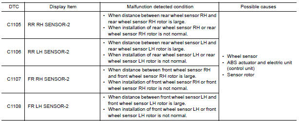
Nissan Maxima Service and Repair Manual: C1105, C1106, C1107, C1108 wheel sensor
DTC Logic
DTC DETECTION LOGIC
DTC CONFIRMATION PROCEDURE
1.CHECK SELF DIAGNOSTIC RESULT
With CONSULT.
- Start engine and drive vehicle at approximately 21 km/h (13 MPH) or more for approximately 5 minutes.
- Perform self diagnostic result
Diagnosis Procedure
CAUTION: Do not check between wheel sensor terminals.
1.CONFIRM DTC
With CONSULT
- Perform self-diagnostic result of ABS and record all active DTCs.
- Clear all DTCs.
- Perform DTC confirmation procedure
2.CHECK TIRE PRESSURE AND TIRE WEAR
Check tires for excessive wear and proper inflation
3.CHECK WHEEL SENSOR
Check wheel sensor for the following:
- Proper installation
- Physical damage
- Contamination
4.CHECK SENSOR ROTOR
Check sensor rotor for the following:
- Contamination
- Physical damage (missing teeth, cracks, etc.)
- Foreign material
- Looseness
5.CONFIRM REPAIR
With CONSULT
- Clear all DTCs.
- Perform DTC confirmation procedure
 C1101, C1102, C1103, C1104 wheel sensor
DTC Logic
DTC DETECTION LOGIC
DTC CONFIRMATION PROCEDURE
1.CHECK SELF DIAGNOSTIC RESULT
With CONSULT.
Start engine and drive vehicle at approximately 21 km/h (13 MPH)
or more for approx ...
 C1109 battery voltage [abnormal]
Description
Supplies electric power to the ABS actuator and electric unit (control unit).
DTC Logic
DTC DETECTION LOGIC
DTC CONFIRMATION PROCEDURE
1.CHECK SELF-DIAGNOSIS RESULTS
Check the se ...
Other materials:
Periodic maintenance
FOR USA AND CANADA
FOR USA AND CANADA : Introduction of Periodic Maintenance
The following tables show the normal maintenance schedule. Depending upon
weather and atmospheric conditions,
varying road surfaces, individual driving habits and vehicle usage, additional
or more frequent maintenan ...
Child safety
WARNING
Do not allow children to play with the seat
belts. Most seating positions are
equipped with Automatic Locking Retractor
(ALR) mode seat belts. If the seat belt
becomes wrapped around a child's neck
with the ALR mode activated, the child can
be seriously injured or killed if the seat
...
Change intervals
The oil and oil filter change intervals for your
engine are based on the use of the specified
quality oils and filters. Using engine oil and filters
that are not of the specified quality, or exceeding
recommended oil and filter change intervals
could reduce engine life. Damage to the engine
ca ...
Nissan Maxima Owners Manual
- Illustrated table of contents
- Safety-Seats, seat belts and supplemental restraint system
- Instruments and controls
- Pre-driving checks and adjustments
- Monitor, climate, audio, phone and voice recognition systems
- Starting and driving
- In case of emergency
- Appearance and care
- Do-it-yourself
- Maintenance and schedules
- Technical and consumer information
Nissan Maxima Service and Repair Manual

0.0076