Nissan Maxima Service and Repair Manual: C1101, C1102, C1103, C1104 wheel sensor
DTC Logic
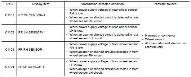
DTC DETECTION LOGIC
DTC CONFIRMATION PROCEDURE
1.CHECK SELF DIAGNOSTIC RESULT
With CONSULT.
- Start engine and drive vehicle at approximately 21 km/h (13 MPH) or more for approximately 5 minutes.
- Perform self diagnostic result.
Diagnosis Procedure
CAUTION: Do not check between wheel sensor terminals.
1.CONFIRM DTC
With CONSULT
- Perform self-diagnostic result of ABS and record all active DTCs.
- Clear all DTCs.
- Perform DTC confirmation procedure.
2.INSPECT WHEEL SENSOR
Inspect the suspect wheel sensor for damage or deformation.
3.HARNESS AND CONNECTOR INSPECTION
- Disconnect ABS actuator and electric unit (control unit) connector E26 and wheel sensor connector of suspect wheel.
- Check harness, connectors and terminals for corrosion, deformation, disconnection, looseness or damage.
4.CHECK WHEEL SENSOR OUTPUT SIGNAL
- Connect ABS active wheel sensor tester (J-45741) to wheel sensor using appropriate adapter.
- Turn on the ABS active wheel sensor tester power switch. NOTE: The green POWER indicator should illuminate. If the POWER indicator does not illuminate, replace the battery in the ABS active wheel sensor tester before proceeding.
- Spin the wheel of the vehicle by hand and observe the red SENSOR indicator on the ABS active wheel sensor tester. The red SENSOR indicator should flash on and off to indicate an output signal. NOTE: If the red SENSOR indicator illuminates but does not flash, reverse the polarity of the tester leads and retest.
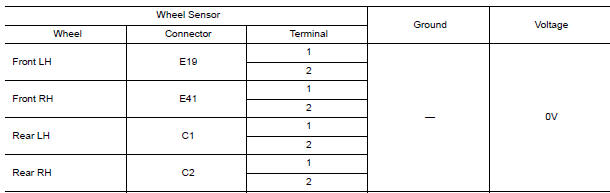
5.CHECK WIRING HARNESS FOR SHORT TO VOLTAGE
- Turn ignition switch ON.
- Check voltage between wheel sensor harness connector terminals of suspect wheel and ground.
6.CHECK WIRING HARNESS FOR SHORT TO GROUND
- Turn ignition switch OFF.
- Check continuity between wheel sensor harness connector terminals of suspect wheel and ground.

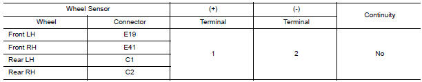
7.CHECK WIRING HARNESS FOR SHORT BETWEEN CIRCUITS
Check continuity between wheel sensor harness connector terminals of suspect wheel.
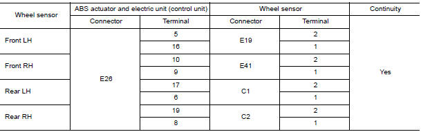
8.CHECK WIRING HARNESS FOR OPEN CIRCUIT
Check continuity between ABS actuator and electric unit (control unit) connector E26 and wheel sensor connector of wheel with DTC.
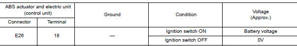
9.CHECK ABS ACTUATOR AND ELECTRIC UNIT (CONTROL UNIT) POWER SUPPLY CIRCUIT
- Turn ignition switch ON.
- Check voltage between ABS actuator and electric unit (control unit) harness connector E26 terminal and ground.
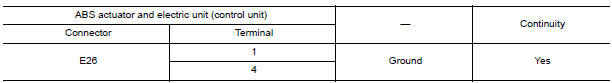
10.CHECK ABS ACTUATOR AND ELECTRIC UNIT (CONTROL UNIT) GROUND CIRCUIT
- Turn ignition switch OFF.
- Check continuity between ABS actuator and electric unit (control unit) connector E26 terminals and ground.
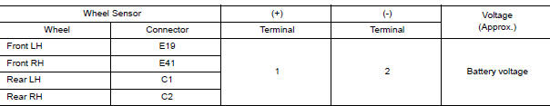
11.CHECK WHEEL SENSOR INPUT VOLTAGE
- Connect ABS actuator and electric unit (control unit) connector E26.
- Turn ignition switch ON.
- Check voltage between suspect wheel sensor harness connector terminals.
12.CONFIRM REPAIR
With CONSULT
- Clear all DTCs.
- Perform DTC confirmation procedure.

 C1105, C1106, C1107, C1108 wheel sensor
DTC Logic
DTC DETECTION LOGIC
DTC CONFIRMATION PROCEDURE
1.CHECK SELF DIAGNOSTIC RESULT
With CONSULT.
Start engine and drive vehicle at approximately 21 km/h (13 MPH)
or more for approx ...
Other materials:
Diagnosis system (bluetooth control unit)
Diagnosis Description
The Bluetooth control unit has two diagnostic checks. The first diagnostic
check is performed automatically every ignition cycle during control unit
initialization. The second diagnostic check is performed by the technician
using the steering wheel audio control switches ...
NISSAN Vehicle Immobilizer System keys
You can only drive your vehicle using the Intelligent
Keys which are registered to the NISSAN
Vehicle Immobilizer System components in your
vehicle.
The mechanical key can be used for all the locks.
Never leave the keys in the vehicle.
Additional or replacement keys:
If you still have a key ...
Main line between A-bag and ABS circuit
Diagnosis Procedure
1.CHECK CONNECTOR
Turn the ignition switch OFF.
Disconnect the battery cable from the negative terminal.
Check the following terminals and connectors for damage, bend and
loose connection (connector side
and harness side).
Harness connector M1
Harness connect ...
Nissan Maxima Owners Manual
- Illustrated table of contents
- Safety-Seats, seat belts and supplemental restraint system
- Instruments and controls
- Pre-driving checks and adjustments
- Monitor, climate, audio, phone and voice recognition systems
- Starting and driving
- In case of emergency
- Appearance and care
- Do-it-yourself
- Maintenance and schedules
- Technical and consumer information
Nissan Maxima Service and Repair Manual

0.0074