Nissan Maxima Service and Repair Manual: Removal and Installation
REMOVAL
- Disconnect the battery negative terminal. Refer to PG-67, "Removal and Installation (Battery)".
- Disconnect the harness connector from the accelerator position sensor.
- Remove the three accelerator pedal nuts.
- Remove the accelerator pedal and accelerator position sensor assembly.
- For electrical inspection of the accelerator pedal position sensor. Refer to EC-469, "Component Inspection".
CAUTION:
- Do not disassemble the pedal assembly. Do not remove the accelerator pedal position sensor from the pedal assembly.
- Avoid impact from dropping during handling.
- Keep the pedal assembly away from water.
INSTALLATION
Installation is in the reverse order of removal.
- Align and install accelerator pedal and accelerator position sensor assembly with locating pins in locating pin holes.
- Check the accelerator pedal for smooth operation. There should be no binding or sticking when applying or releasing the accelerator pedal.
Check that the accelerator pedal moves through the full specified distance of pedal trav
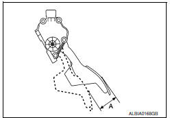
Pedal travel (A) : Refer to ACC-5, "Accelerator Control".
CAUTION: Whenever the harness connector of the accelerator pedal position sensor is disconnected, perform the "Accelerator pedal released position learning". Refer to EC-20, "ACCELERATOR PEDAL RELEASED POSITION LEARNING : Special Repair Requirement".
 Exploded View
Accelerator pedal and accelerator position sensor assembly
Locating pins Front
...
 Service data and specifications (SDS)
SERVICE DATA AND SPECIFICATIONS (SDS)
Accelerator Control
PEDAL TRAVEL
Accelerator pedal - total travel (A) 48.5 - 53.5 mm (1.91 - 2.11 in) ...
Other materials:
System description
REFRIGERATION SYSTEM
Refrigerant Cycle
Refrigerant flow
Compressor
Pressure relief valve
Liquid tank
Refrigerant pressure sensor
Condenser
Expansion valve
Evaporator
Blower motor
High-pressure gas
High-pressure liquid
Low-pressure liquid
Low-pr ...
Satellite radio antenna
Removal and Installation
REMOVAL
Lower the headlining at the rear. Refer to INT-33, "Exploded View".
Disconnect the harness connector (A) from satellite radio
antenna.
Remove the satellite radio antenna nut (B) and the satellite radio
antenna (1).
INSTALLATION
Instal ...
Back-up lamp
Wiring Diagram
...
Nissan Maxima Owners Manual
- Illustrated table of contents
- Safety-Seats, seat belts and supplemental restraint system
- Instruments and controls
- Pre-driving checks and adjustments
- Monitor, climate, audio, phone and voice recognition systems
- Starting and driving
- In case of emergency
- Appearance and care
- Do-it-yourself
- Maintenance and schedules
- Technical and consumer information
Nissan Maxima Service and Repair Manual

0.0051