Nissan Maxima Service and Repair Manual: Exploded View
Nissan Maxima Service and Repair Manual / Engine / Accelerator control system / Removal and installation / Exploded View
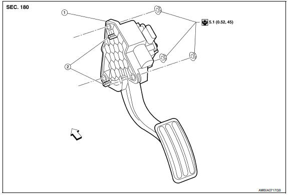
- Accelerator pedal and accelerator position sensor assembly
- Locating pins
 Front
Front

 Removal and Installation
REMOVAL
Disconnect the battery negative terminal. Refer to PG-67, "Removal
and Installation (Battery)".
Disconnect the harness connector from the accelerator position
sensor.
Remove the ...
Other materials:
Dehumidified defrosting or defogging
1. Press the front
defroster button on.
2. Turn the temperature control dial to set the
maximum temperature to aid in defrosting or
defogging.
To quickly remove ice from the outside of the
windows, use the fan speed
control
buttons to set the fan speed to maximum.
As soon ...
Vehicle security system
Wiring Diagram
...
Front door speaker
Description
The AV control unit sends audio signals to the front door speakers using the
front door speaker circuits.
Diagnosis Procedure
1.CONNECTOR CHECK
Check the AV control unit and speaker connectors for the following:
Proper connection
Damage
Disconnected or loose terminals
2. ...
Nissan Maxima Owners Manual
- Illustrated table of contents
- Safety-Seats, seat belts and supplemental restraint system
- Instruments and controls
- Pre-driving checks and adjustments
- Monitor, climate, audio, phone and voice recognition systems
- Starting and driving
- In case of emergency
- Appearance and care
- Do-it-yourself
- Maintenance and schedules
- Technical and consumer information
Nissan Maxima Service and Repair Manual

© 2017-2026 Copyright www.nimainfo.com
0.0072
0.0072