Nissan Maxima Service and Repair Manual: Service data and specifications (SDS)
SERVICE DATA AND SPECIFICATIONS (SDS)
Accelerator Control
PEDAL TRAVEL
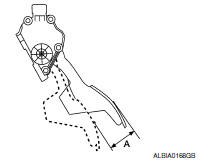
Accelerator pedal - total travel (A) 48.5 - 53.5 mm (1.91 - 2.11 in)
 Removal and Installation
REMOVAL
Disconnect the battery negative terminal. Refer to PG-67, "Removal
and Installation (Battery)".
Disconnect the harness connector from the accelerator position
sensor.
Remove the ...

Other materials:
Center speaker
Description
The audio unit sends audio signals to the BOSE speaker amp. The BOSE speaker
amp. amplifies the audio signals before sending them to the center speaker
using the audio signal circuits.
Diagnosis Procedure
1.CONNECTOR CHECK
Check the audio unit, BOSE speaker amp. and speaker conne ...
Steering switch
Removal and Installation
REMOVAL
Remove the driver airbag module. Refer to SR-12, "Removal and
Installation".
Remove the steering wheel audio control switch screws (A).
Release the steering wheel audio control switch harness clips
(B).
Remove the steering wheel audio control switc ...
Additional service when replacing transaxle assembly
Description
When replacing the transaxle assembly, perform the following work.
ERASING, LOADING AND STORING OF CALIBRATION DATA
The TCM acquires calibration data (individual characteristic
value) of each solenoid that is stored in the
ROM assembly (in the control valve). This enabl ...
Nissan Maxima Owners Manual
- Illustrated table of contents
- Safety-Seats, seat belts and supplemental restraint system
- Instruments and controls
- Pre-driving checks and adjustments
- Monitor, climate, audio, phone and voice recognition systems
- Starting and driving
- In case of emergency
- Appearance and care
- Do-it-yourself
- Maintenance and schedules
- Technical and consumer information
Nissan Maxima Service and Repair Manual

0.0071