Nissan Maxima Service and Repair Manual: Seat cushion thermal electric device
Description
Provides cooling and heat for the seat cushion.
Component Function Check
1.CHECK SEAT CUSHION THERMAL ELECTRIC DEVICE FUNCTION
- Turn the climate controlled seat switch to the H (Heat) HI position and check that the seat cushion thermal electric device operates correctly.
- Turn the climate controlled seat switch to the C (Cool) HI position and check that the seat cushion thermal electric device operates correctly.
Diagnosis Procedure
Regarding Wiring Diagram information, refer to SE-44, "Wiring Diagram".
1.CHECK SEAT CUSHION THERMAL ELECTRIC DEVICE
Perform thermal electric device component inspection for the seat cushion. Refer to SE-16, "Component Inspection (Thermal Electric Device)".
2.CHECK SEAT CUSHION THERMAL ELECTRIC DEVICE CIRCUITS
- Turn ignition switch OFF.
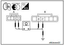
- Disconnect seat cushion thermal electric device connector and climate controlled seat control unit connector B217.
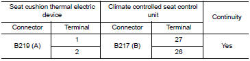
- Check continuity between seat cushion thermal electric device connector B219 (A) terminals 1, 2 and climate controlled seat control unit connector B217 (B) terminals 26, 27.
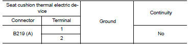
4. Check continuity between seat cushion thermal electric device connector B219 (A) terminals 1, 2 and ground.
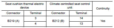
3.CHECK SEAT CUSHION THERMAL ELECTRIC DEVICE SENSOR CIRCUITS
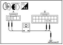
- Disconnect climate controlled seat control unit connector B212.
- Check continuity between seat cushion thermal electric device connector B219 (A) terminals 3, 4 and climate controlled seat control unit connector B212 (B) terminals 13, 14.
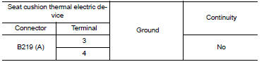
3. Check continuity between seat cushion thermal electric device connector B219 (A) terminals 3, 4 and ground.
Component Inspection (Thermal Electric Device)
1.CHECK THERMAL ELECTRIC DEVICE
- Turn ignition switch OFF.
- Disconnect thermal electric device connector.
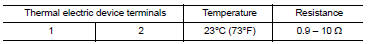
- Measure the resistance of the thermal electric device between terminals 1 and 2.
NOTE:
The resistance value in the table below will change under any of the following conditions:
- air blowing across the thermal electric device
- changing the surrounding temperature of the thermal electric device
- measuring at other than 23C (73F)
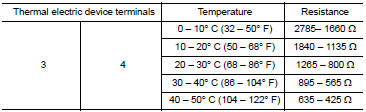
2.CHECK THERMAL ELECTRIC DEVICE SENSOR
Measure the resistance of the thermal electric device sensor between terminals 3 and 4.
 Climate controlled seat blower motor
Description
Sends airflow to the seat cushion and seatback.
Component Function Check
1.CHECK CLIMATE CONTROLLED SEAT BLOWER MOTOR FUNCTION
Turn the climate controlled seat switch to the H (Heat) L ...
 Seatback thermal electric device
Description
Provides cooling and heat for the seatback.
Component Function Check
1.CHECK SEATBACK THERMAL ELECTRIC DEVICE FUNCTION
Turn the climate controlled seat switch to the H (Heat) HI
...
Other materials:
AV control unit
Removal and Installation
AV control unit
AV control unit bracket (LH)
AV control unit bracket (RH)
A/C auto amp.
Cluster lid C (with A/C and AV switch
assembly attached)
Clip
AV CONTROL UNIT
Removal
CAUTION:
Before replacing AV control unit, perform "READ CONFIGU ...
Rear window defogger and door mirror defogger do not
operate
Diagnosis Procedure
1. CHECK REAR WINDOW DEFOGGER SWITCH
Check rear window defogger switch.
2. CHECK REAR WINDOW DEFOGGER RELAY
Check rear window defogger relay
3. CHECK FUSES
Check if any of the following fuses in fuse block (J/B) are blown.
4. CHECK REAR WINDOW DEFOGGER POWER SUPPLY CIR ...
Telescopic motor
Exploded View
Steering column assembly
Telescope motor
Telescope motor link bracket
Tilt motor
Tilt motor bolt cap
Removal and Installation
REMOVAL
Remove instrument lower panel LH. Refer to IP-19, "Removal and
Installation".
Remove lower knee protector (LH) bolts (A) a ...
Nissan Maxima Owners Manual
- Illustrated table of contents
- Safety-Seats, seat belts and supplemental restraint system
- Instruments and controls
- Pre-driving checks and adjustments
- Monitor, climate, audio, phone and voice recognition systems
- Starting and driving
- In case of emergency
- Appearance and care
- Do-it-yourself
- Maintenance and schedules
- Technical and consumer information
Nissan Maxima Service and Repair Manual

0.01