Nissan Maxima Service and Repair Manual: Climate controlled seat blower motor
Description
Sends airflow to the seat cushion and seatback.
Component Function Check
1.CHECK CLIMATE CONTROLLED SEAT BLOWER MOTOR FUNCTION
Turn the climate controlled seat switch to the H (Heat) LO, MED, and HI positions and the C (Cool) LO, MED, and HI positions. Check that the climate controlled seat blower motor operates at low, medium and high speed.
Diagnosis Procedure
Regarding Wiring Diagram information, refer to SE-44, "Wiring Diagram".
1.CHECK CLIMATE CONTROLLED SEAT BLOWER MOTOR
Perform climate controlled seat blower motor component inspection. Refer to SE-14, "Component Inspection (Climate Controlled Seat Blower Motor)".
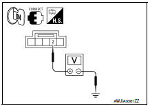
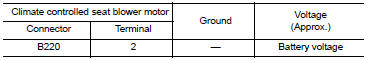
2.CHECK CLIMATE CONTROLLED SEAT BLOWER MOTOR POWER SUPPLY
- Turn ignition switch ON.
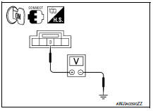
- Check voltage between climate controlled seat blower motor connector B220 terminal 2 and ground.
3.CHECK CLIMATE CONTROLLED SEAT BLOWER MOTOR POWER SUPPLY CIRCUIT
- Turn ignition switch OFF.
- Disconnect climate controlled seat blower motor connector and climate controlled seat control unit connector B212.
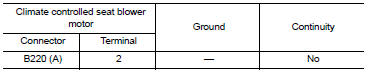
- Check continuity between climate controlled seat blower motor connector B220 (A) terminal 2 and climate controlled seat control unit connector B212 (B) terminal 7.
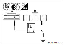
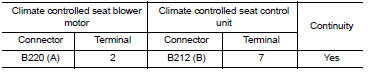
4. Check continuity between climate controlled seat blower motor connector B220 (A) terminal 2 and ground.
4.CHECK CLIMATE CONTROLLED SEAT BLOWER MOTOR SPEED CONTROL SIGNAL
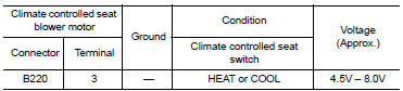
Check voltage between climate controlled seat blower motor connector B220 terminal 3 and ground.
5.CHECK CLIMATE CONTROLLED SEAT BLOWER MOTOR SPEED CONTROL SIGNAL CIRCUIT
- Turn ignition switch OFF.
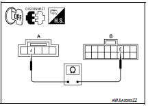
- Disconnect climate controlled seat blower motor connector and climate controlled seat control unit connector B212.
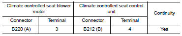
- Check continuity between climate controlled seat blower motor connector B220 (A) terminal 3 and climate controlled seat control unit connector B212 (B) terminal 4.
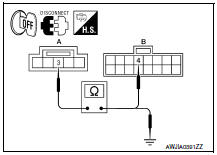
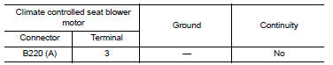
4. Check continuity between climate controlled seat blower motor connector B220 (A) terminal 3 and ground.
6.CHECK CLIMATE CONTROLLED SEAT BLOWER MOTOR GROUND CIRCUIT
- Turn ignition switch OFF.
- Disconnect climate controlled seat blower motor connector and climate controlled seat control unit connector B212.
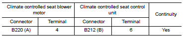
- Check continuity between climate controlled seat blower motor connector B220 (A) terminal 4 and climate controlled seat control unit connector B212 (B) terminal 6.
Component Inspection (Climate Controlled Seat Blower Motor)
1.CHECK CLIMATE CONTROLLED SEAT BLOWER MOTOR PART 1
- Turn ignition switch OFF.
- Disconnect climate controlled seat blower motor connector.
- Measure the resistance of the climate controlled seat blower motor between terminals 2 and 4.
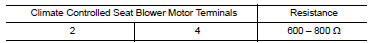
2.CHECK CLIMATE CONTROLLED SEAT BLOWER MOTOR PART 2
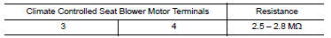
Measure the resistance of the climate controlled seat blower motor between terminals 3 and 4.
 Power supply and ground circuit
CLIMATE CONTROLLED SEAT CONTROL UNIT
CLIMATE CONTROLLED SEAT CONTROL UNIT : Diagnosis Procedure
Regarding Wiring Diagram information, refer to SE-44, "Wiring Diagram".
1.CHECK FUSES
2.CHECK BATT ...
 Seat cushion thermal electric device
Description
Provides cooling and heat for the seat cushion.
Component Function Check
1.CHECK SEAT CUSHION THERMAL ELECTRIC DEVICE FUNCTION
Turn the climate controlled seat switch to the H (Heat ...
Other materials:
Hazard switch
Component Function Check
1.CHECK HAZARD SWITCH SIGNAL BY CONSULT
CONSULT DATA MONITOR
Turn ignition switch ON.
Select "HAZARD SW" of BCM (FLASHER) DATA MONITOR item.
With operating the hazard switch, check the monitor status.
Diagnosis Procedure
1.CHECK HAZARD SWITCH SIGNAL INPUT
...
Fuel gauge
The gauge indicates the approximate fuel level
in the tank.
The gauge may move slightly during braking,
turning, acceleration, or going up or down hills.
The gauge needle returns to 0 (Empty) after the
ignition switch is placed in the OFF position.
The low fuel warning message shows in ...
Seat memory switch
Description
Seat memory switch is installed to the front door LH trim. The operation
signal is input to the driver seat control unit when the seat memory switch
is operated.
Component Function Check
1. CHECK FUNCTION
Select ""MEMORY SW 1", "MEMORY SW 2", "SET SW" in "DATA MONITOR"
mode ...
Nissan Maxima Owners Manual
- Illustrated table of contents
- Safety-Seats, seat belts and supplemental restraint system
- Instruments and controls
- Pre-driving checks and adjustments
- Monitor, climate, audio, phone and voice recognition systems
- Starting and driving
- In case of emergency
- Appearance and care
- Do-it-yourself
- Maintenance and schedules
- Technical and consumer information
Nissan Maxima Service and Repair Manual

0.0055