Nissan Maxima Service and Repair Manual: Power supply and ground circuit
CLIMATE CONTROLLED SEAT CONTROL UNIT
CLIMATE CONTROLLED SEAT CONTROL UNIT : Diagnosis Procedure
Regarding Wiring Diagram information, refer to SE-44, "Wiring Diagram".
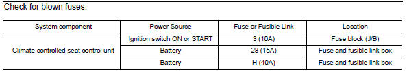
1.CHECK FUSES
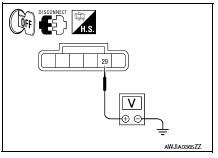
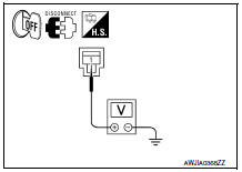
2.CHECK BATTERY POWER SUPPLY CIRCUIT
- Turn ignition switch OFF.
- Disconnect climate controlled seat control unit connector B217.
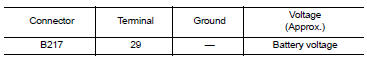
- Check voltage between climate controlled seat control unit connector B217 terminal 29 and ground.
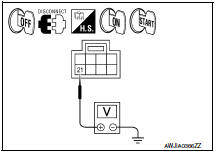
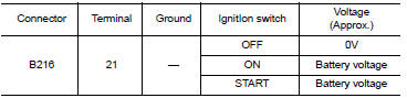
3.CHECK IGNITION POWER SUPPLY CIRCUIT
- Disconnect climate controlled seat control unit connector B216.
- Check voltage between climate controlled seat control unit connector B216 terminal 21 and ground.
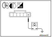
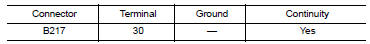
4.CHECK GROUND CIRCUIT
- Turn ignition switch OFF.
- Check continuity between climate controlled seat control unit connector B217 terminal 30 and ground.
5.CHECK CLIMATE CONTROLLED SEAT RELAY
Perform the climate controlled seat relay component inspection. Refer to SE-10, "CLIMATE CONTROLLED SEAT CONTROL UNIT : Component Inspection (Climate Controlled Seat Relay)".
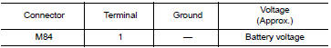
6.CHECK CIRCUIT BREAKER POWER SUPPLY CIRCUIT
- Disconnect the circuit breaker connector M84.
- Check voltage between circuit breaker connector M84 terminal 1 and ground.
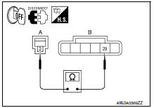
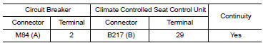
7.CHECK BATTERY POWER SUPPLY CIRCUIT FOR OPEN
Check continuity between circuit breaker connector M84 (A) terminal 2 and climate controlled seat control unit connector B217 (B) terminal 29.
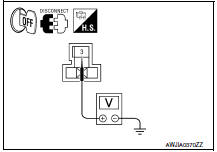
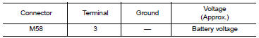
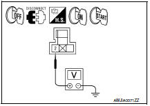
8.CHECK CLIMATE CONTROLLED SEAT RELAY BATTERY POWER SUPPLY CIRCUIT
- Disconnect climate controlled seat relay connector.
- Check voltage between climate controlled seat relay connector M58 terminal 3 and ground.
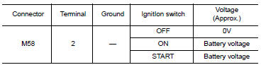
9.CHECK CLIMATE CONTROLLED SEAT RELAY IGNITION POWER SUPPLY CIRCUIT
Check voltage between climate controlled seat relay connector M58 terminal 2 and ground.
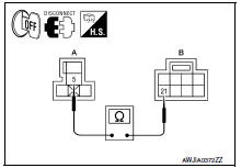
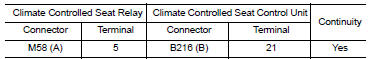
10.CHECK IGNITION POWER SUPPLY CIRCUIT FOR OPEN
Check continuity between climate controlled seat relay connector M58 (A) terminal 5 and climate controlled seat control unit connector B216 (B) terminal 21.
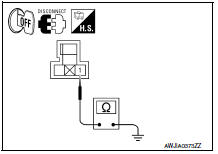
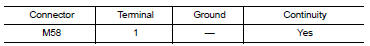
11.CHECK CLIMATE CONTROLLED SEAT RELAY GROUND CIRCUIT
Check continuity between climate controlled seat relay connector M58 terminal 1 and ground.
CLIMATE CONTROLLED SEAT CONTROL UNIT : Component Inspection (Climate Controlled Seat Relay)
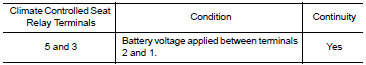
1.CHECK CLIMATE CONTROLLED SEAT RELAY
- Apply battery voltage between terminals 2 and 1 of the climate controlled seat relay. CAUTION: Connect a fuse between the terminals when applying battery voltage.
- Check continuity between climate controlled seat relay terminals 5 and 3.

 Climate controlled seat blower motor
Description
Sends airflow to the seat cushion and seatback.
Component Function Check
1.CHECK CLIMATE CONTROLLED SEAT BLOWER MOTOR FUNCTION
Turn the climate controlled seat switch to the H (Heat) L ...
Other materials:
B2110 transmission range switch
Description
IPDM E/R confirms the shift position with the following
signals.
Transmission range switch
Shift position signal from BCM (CAN)
DTC Logic
DTC DETECTION LOGIC
NOTE:
If DTC B2110 is displayed with DTC
U1000, first perform the trouble diagnosi ...
Fuel pump
Description
*: ECM determines the start signal status by the signals of engine speed and
battery voltage.
The ECM activates the fuel pump for several seconds after the ignition switch is
turned ON to improve engine
start ability. If the ECM receives a engine speed signal from the camsh ...
BSW system operation
1. Side BSW/RCTA Indicator Light
2. BSW/RCTA Indicator
The BSW system operates above approximately
20 mph (32km/h).
If the radar sensors detect a vehicle in the detection
zone, the side BSW/RCTA indicator light (1)
illuminates. If the turn signal is then activated, the
system chimes (tw ...
Nissan Maxima Owners Manual
- Illustrated table of contents
- Safety-Seats, seat belts and supplemental restraint system
- Instruments and controls
- Pre-driving checks and adjustments
- Monitor, climate, audio, phone and voice recognition systems
- Starting and driving
- In case of emergency
- Appearance and care
- Do-it-yourself
- Maintenance and schedules
- Technical and consumer information
Nissan Maxima Service and Repair Manual

0.0059