Nissan Maxima Service and Repair Manual: Front seat
DRIVER SIDE
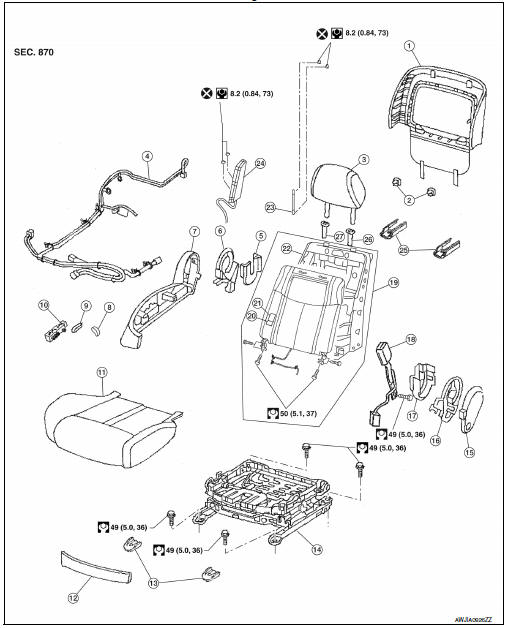
DRIVER SIDE : Exploded View
Driver Seat - With Climate Controlled Seats
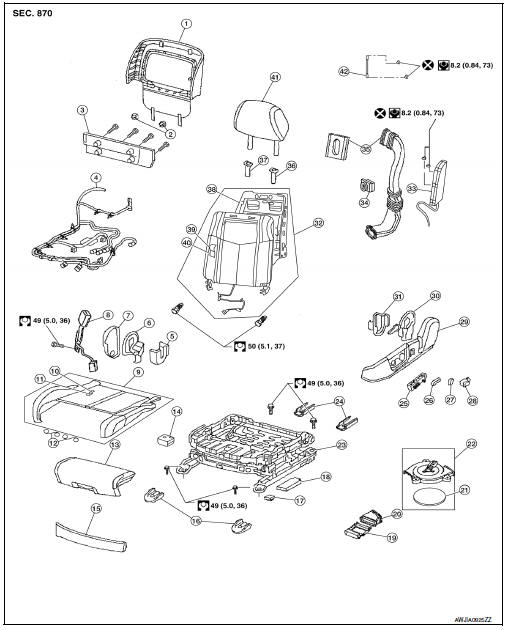
- Seatback board
- Seatback board clip
- Seat cushion lower rear finisher
- Seat harness
- Seat cushion inner finisher inside (RH)
- Recline mechanism inner cover
- Seat cushion outer finisher (RH)
- Seat belt buckle
- Seat cushion assembly
- Seat cushion trim
- Seat cushion pad
- Thigh extension tether
- Thigh extension assembly
- Climate controlled seat control unit
- Seat cushion front finisher
- Front slide cover
- Clip
- Power seat control unit
- Seat cushion thermal electric device (TED)
- Lower seat duct
- Climate controlled seat blower filter
- Climate controlled seat blower motor assembly
- Seat frame assembly
- Rear slide cover
- Power seat switch
- Seat slide and lifter switch knob
- Seat recline knob
- Lumbar support switch
- Seat cushion outer finisher (LH)
- Recline device outer cover
- Seat cushion inner finisher inside (LH)
- Seatback assembly
- Side air bag module
- Seatback thermal electric device (TED)
- Upper seat duct
- Headrest holder (locked)
- Headrest holder (free)
- Seatback frame
- Seatback trim
- Seatback pad
- Headrest
- Chute rod
DRIVER SIDE : Disassembly and Assembly
SEAT ASSEMBLY WITH SIDE AIR BAG MODULE
WARNING:
Do not leave any objects (screwdriver, tools, etc.) on the seat during seatback repair. It can lead to personal injury if the side air bag should accidentally deploy.
CAUTION:
- Before servicing, turn the ignition switch OFF, disconnect both battery terminals and wait at least three minutes.
- Handle the side air bag module carefully. During disassembly, always hold the side air bag module, do not let it hang by the wire harness.
- Always place side air bag module with the stud bolt side facing downward.
- Always work from the side or back of the seatback assembly, do not work in front of the seat.
- Do not use air tools or electric tools when servicing the seat assembly.
- Replace the side air bag module if it has been dropped or sustained an impact.
- Do not insert any objects into the side air bag module.
- Do not disassemble the side air bag module.
- Do not expose the side air bag module to temperatures exceeding 93C (200F).
- Do not expose the side air bag module to any oil, grease or water.
- During disassembly, do not damage the trim cover, chutes, connectors, retainers, clips, module harness or the side air bag module.
NOTE:
- If the vehicle has been involved in a collision and the side air bag has deployed, the front seatback assembly must be replaced.
- For side air bag module removal and installation, refer to SR-21, "Removal and Installation".
Disassembly
- Remove the front seat assembly. Refer to SE-68, "Removal and Installation".
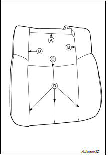
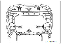
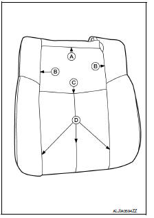
- Remove the seatback board as follows:
NOTE:
The seatback board is attached to the seat frame with the following:
- Two top hooks (A)
- Two side hooks (B)
- Two bottom retainers (C)
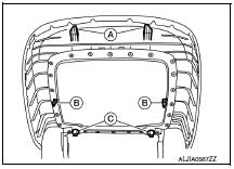
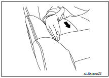
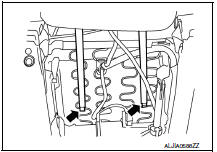
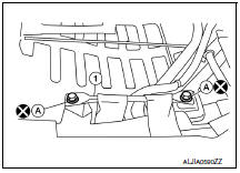
a. From the bottom of the seat, unhook the two seat skirt hooks as shown.

b. Carefully pull upward on the lower seatback board to release the two bottom retainers (C).
CAUTION:
Do not pull outward at two top hooks (A)
c. Hold the seatback board at the side hook locations (B) and push in the side hooks to release them from the seatback frame, then pull it rearward.
d. Carefully pull the seatback board downward to disengage the top hooks as shown.
CAUTION:
Use care not to break the seatback board hooks and retainers. Replace seatback board if any hooks or retainers are damaged.
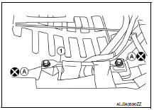
3. Disconnect the upper seat duct. 4. Remove and discard the two chute rod bolts (A), then remove the chute rod (1).
CAUTION:
Do not reuse the chute rod bolts.
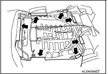
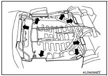
5. Release the seven seatback retainers from the seatback frame as shown.
6. Reach in from the bottom of the seatback to release the guide clips on the headrest holder. Squeeze the clips at the bottom and push upward to remove as shown.
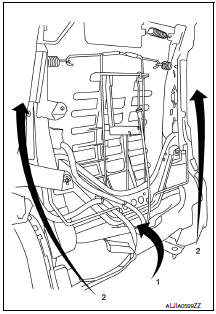
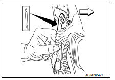
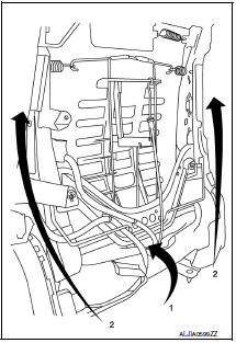
7. Push the seatback trim and seatback pad forward at the bottom (1), then holding the seatback assembly on both sides, lift upward (2). Remove the seatback trim and seatback pad as an assembly from the seatback frame.
8. If required, separate the seatback trim from the seatback pad as follows:
NOTE:
The seatback trim is attached to the seatback pad with the following:
- Five top hog rings (A)
- Four side hog rings (B)
- Three middle hog rings (C)
- Three bottom velcro fasteners (D)
a. Pull the seatback trim from the seatback pad to detach the velcro fasteners. b. Position the seatback trim to access the middle hog rings. Remove the middle and side hog rings. c. Remove the top hog rings, then separate the seatback trim from the seatback pad.
Assembly
Assembly is in the reverse order of disassembly. During assembly, note the following.
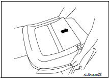
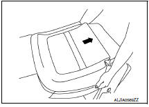
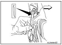
- When installing the seatback trim, firmly push down while sliding your hand along the seams as shown (arrow) to ensure the velcro fasteners are fastened properly.
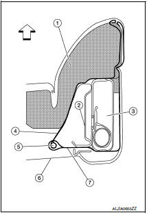
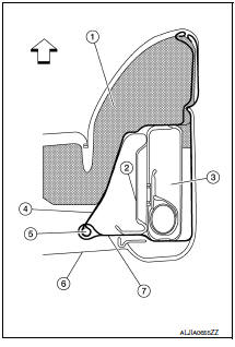
- Make sure the chute rod is properly positioned and installed as shown.
 : Front
- Make sure the side air bag outer chute (7) is pulled over the side
air bag module (3) and the side air bag inner chute (4) is pulled
around the frame (2). Make sure there are no wrinkles and the
chutes are not folded, twisted or pinched.
(1) Seatback pad
(5) Chute rod
(6) Seatback board
 : Front
CAUTION:
- If a malfunction was detected by the air bag warning lamp, after repair or replacement of the malfunction parts, reset the memory using self-diagnosis or CONSULT.
- After work is completed, check that no system malfunction is detected by air bag warning lamp.
- Make sure side air bag module shell is closed at all tabs and cushion of module is not exposed. Do not reuse if the tab of shell is not secured.
- Always install new side air bag module attaching nuts and side air bag chute rod bolts.
- Always route side air bag module harness in original location. Replace any deformed or damaged clips with the same type and color. Always install clips in the original location on the harness.
- Smooth out all wrinkles during assembly.
- Inspect seatback pad, trim cover and trim cover chutes. Replace if damaged.
- Replace any deformed or damaged parts.
- Replace any deformed or damaged hog rings. Ensure any old hog ring pieces are removed from the seat.
- Use only one hog ring in each designated location.
- Ensure hog rings are correctly fastened around both the seatback trim and seatback pad trim wires.
NOTE:
Use NISSAN standard hog rings and tools to assemble.
SEAT CUSHION THERMAL ELECTRIC DEVICE AND LOWER SEAT DUCT
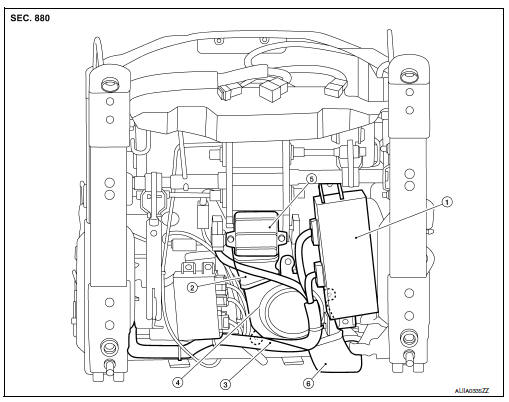
- Seat control unit
- Lower seat duct
- Seat wire harness
- Climate controlled seat blower motor
- Seat cushion thermal electric device
- Upper seat duct
Disassembly
- Remove the seat from the vehicle. Refer to SE-68, "Removal and Installation".
- Remove seatback board.
- Remove seat cushion rear finisher.
- Disconnect the harness connectors from the driver seat control unit.
- Remove driver seat control unit from seat.
- Remove seat cushion thermal electric device bolts.
- Remove climate controlled seat blower motor bolts.
- Disconnect climate controlled seat blower motor from upper seat duct.
- Remove climate controlled seat blower motor, lower seat duct and seat cushion thermal electric device from seat.
Assembly
Assembly is in the reverse order of disassembly.
THIGH EXTENSION ASSEMBLY
Disassembly
- Move the thigh extension assembly to the front most position and release the trim cover clips (A).
- Remove the trim cover and pad (B).
3. Cut the thigh extension tethers and drill out the upper rivets (A) that connect the thigh extension tethers (B) to the thigh extension assembly (C).
4. Insert suitable tool into the thigh extension assembly top panel and release the clip (A).
5. Pull the thigh extension handle and remove the thigh extension assembly.
6. Drill out the lower rivets that connect the thigh extension tethers to the seat frame assembly.
Assembly
- Replace the pad, trim and clips to the thigh extension assembly.
- Rivet the thigh extension tethers to the seat frame assembly mounting hole (A).
3. Align the thigh extension assembly on the top rail.
4. Lift the thigh extension handle and slide the thigh extension assembly onto the seat.
5. Rivet the thigh extension tethers to the thigh extension assembly mounting hole (A).
PASSENGER SIDE
PASSENGER SIDE : Exploded View
Passenger Seat
- Seatback board
- Seatback board clips
- Headrest
- Seat harness
- Seat cushion inner finisher inside (RH)
- Recline device inner cover
- Seat cushion outer finisher (RH)
- Seat recline knob
- Seat slide and lifter switch knob
- Power seat switch
- Seat cushion assembly
- Seat cushion front finisher
- Front slide cover
- Seat frame assembly
- Seat cushion outer finisher (LH)
- Recline mechanism inner cover
- Seat cushion inner finisher inside (LH)
- Seat belt buckle
- Seatback assembly
- Seatback pad
- Seatback trim
- Seatback frame
- Chute rod
- Side air bag module
- Rear slide cover
- Headrest holder (locked)
- Headrest holder (free)
PASSENGER SIDE : Disassembly and Assembly
SEAT ASSEMBLY WITH SIDE AIR BAG MODULE
WARNING:
Do not leave any objects (screwdriver, tools, etc.) on the seat during seatback repair. It can lead to personal injury if the side air bag should accidentally deploy.
CAUTION:
- Before servicing, turn the ignition switch OFF, disconnect both battery terminals and wait at least 3 minutes.
- Handle the side air bag module carefully. During disassembly, always hold the side air bag module, do not let it hang by the wire harness.
- Always place side air bag module with the stud bolt side facing downward.
- Always work from the side or back of the seatback assembly, do not work in front of seat.
- Do not use air tools or electric tools when servicing the seat assembly.
- Replace the side air bag module if it has been dropped or sustained an impact.
- Do not insert any objects into the side air bag module.
- Do not disassemble the side air bag module.
- Do not expose the side air bag module to temperatures exceeding 93C (200F)
- Do not expose the side air bag module to any oil, grease or water.
- During disassembly, do not damage the trim cover, chutes, connectors, retainers, clips, module harness or the side air bag module.
NOTE:
- If the vehicle has been involved in a collision and the side air bag has deployed, the front seatback assembly must be replaced.
- For side air bag module removal and installation, refer to SR-21, "Removal and Installation".
Disassembly
- Remove the front seat assembly. Refer to SE-68, "Removal and Installation".
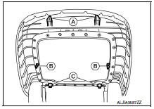
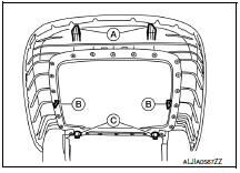
- Remove the seatback board as follows:
NOTE:
The seatback board is attached to the seat frame with the following:
- Two top hooks (A)
- Two side hooks (B)
- Two bottom retainers (C)
a. From the bottom of the seat, unhook the two seat skirt hooks as shown.
b. Carefully pull upward on the lower seatback board to release the two bottom retainers (C).
CAUTION:
Do not pull outward at two top hooks (A).
c. Hold the seatback board at the side hook locations (B) and push in the side hooks to release them from the seatback frame, then pull it rearward.
d. Carefully pull the seatback board downward to disengage the top hooks as shown.
CAUTION:
Use care not to break the seatback board hooks and retainers. Replace seatback board if any hooks or retainers are damaged.
3. Remove and discard the two chute rod bolts (A), then remove the chute rod (1).
CAUTION:
Do not reuse the chute rod bolts.
4. Release the seven seatback retainers from the seatback frame as shown.
5. Reach in from the bottom of the seatback to release the guide clips on the headrest holder. Squeeze the clips at the bottom and push upward to remove as shown.
6. Disconnect the harness connector for the seatback heater.
7. Push the seatback trim and seatback pad forward at the bottom (1), then holding the seatback assembly on both sides, lift upward (2). Remove the seatback trim and seatback pad as an assembly from the seatback frame.
8. If required, separate the seatback trim from the seatback pad as follows:
NOTE:
The seatback trim is attached to the seatback pad with the following:
- Five top hog rings (A)
- Three side hog rings (B)
- Three middle hog rings (C)
- Three bottom velcro fasteners (D)
a. Pull the seatback trim cover from the seatback pad to detach the velcro fasteners. b. Position the seatback trim to access the middle hog rings. Remove the middle and side hog rings. c. Remove the top hog rings, then separate the seatback trim from the seatback pad.
Assembly
Assembly is in the reverse order of disassembly. During assembly, note the following.
- When installing the seatback trim, firmly push down while sliding your hand along the seams as shown (arrow) to ensure the velcro fasteners are fastened properly.
- Make sure the chute rod is properly positioned and installed as
shown.
 : Front
- Make sure the side air bag outer chute (7) is pulled over the side
air bag module (3) and the side air bag inner chute (4) is pulled
around the frame (2). Make sure there are no wrinkles and the
chutes are not folded, twisted or pinched.
(1) Seatback pad
(5) Chute rod
(6) Seatback board
 : Front
CAUTION:
- If a malfunction was detected by the air bag warning lamp, after repair or replacement of the malfunction parts, reset the memory using self-diagnosis or CONSULT.
- After work is completed, check that no system malfunction is detected by air bag warning lamp.
- Make sure side air bag module shell is closed at all tabs and cushion of module is not exposed. Do not reuse if the tab of shell is not secured.
- Always install new side air bag module attaching nuts and side air bag chute rod bolts.
- Always route side air bag module harness in original location. Replace any deformed or damaged clips with the same type and color. Always install clips in the original location on the harness.
- Smooth out all wrinkles during assembly.
- Inspect seatback pad, trim cover and trim cover chutes. Replace if damaged.
- Replace any deformed or damaged parts.
- Replace any deformed or damaged hog rings. Ensure any old hog ring pieces are removed from seat.
- Use only one hog ring in each designated location.
- Ensure hog rings are correctly fastened around both the seatback trim and seatback pad trim wires.
NOTE:
Use NISSAN standard hog rings and tools to assemble.

 Rear seat
Exploded View - Fixed Seatback
Headrest
Headrest holder (free)
Headrest holder (locked)
Bumper
Seatback assembly
Seatback trim
Seatback pad
Seat cushion trim
Seat cushion p ...
Other materials:
ABS branch line circuit
Diagnosis Procedure
1.CHECK CONNECTOR
Turn the ignition switch OFF.
Disconnect the battery cable from the negative terminal.
Check the terminals and connectors of the ABS actuator and
electric unit (control unit) for damage, bend
and loose connection (unit side and connector side).
...
Interior room lamp
Removal and Installation
FRONT ROOM/MAP LAMP ASSEMBLY
Removal
Release the metal clips and drop front edge of front room/map
lamp assembly (1) away from headlining. Slide front room/map lamp
assembly forward in vehicle to clear pawls at rear.
: Front :
Pawl : Metal clip
Disco ...
Refrigerant
Description
CONNECTION OF SERVICE TOOLS AND EQUIPMENT
Shut-off valve
A/C service valve
Recovery/recycling/recharging equipment
Refrigerant container (HFC-134a)
Weight scale (J-39650)
Vacuum pump (J-39649)
Manifold gauge set (J-39183)
Preferred (best) method
A ...
Nissan Maxima Owners Manual
- Illustrated table of contents
- Safety-Seats, seat belts and supplemental restraint system
- Instruments and controls
- Pre-driving checks and adjustments
- Monitor, climate, audio, phone and voice recognition systems
- Starting and driving
- In case of emergency
- Appearance and care
- Do-it-yourself
- Maintenance and schedules
- Technical and consumer information
Nissan Maxima Service and Repair Manual

0.0057