Nissan Maxima Service and Repair Manual: Rear seat
Exploded View - Fixed Seatback
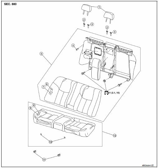
- Headrest
- Headrest holder (free)
- Headrest holder (locked)
- Bumper
- Seatback assembly
- Seatback trim
- Seatback pad
- Seat cushion trim
- Seat cushion pad
- Seat cushion wire cover
- Seat cushion lock
- Seat cushion assembly
Exploded View - 60:40 Split Seatback
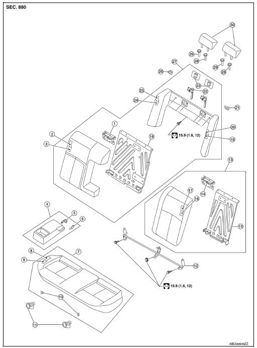
- Seatback latch striker (RH)
- Seatback trim (RH)
- Seatback pad (RH)
- Armrest assembly
- Inner armrest bracket (RH)
- Inner armrest bracket (LH)
- Seat cushion assembly
- Seat cushion trim
- Seat cushion pad
- Seat cushion wire cover
- Seat cushion lock
- Seatback hinge assembly
- Seatback assembly (LH)
- Seatback latch striker (LH)
- Seatback frame (LH)
- Seatback pad (LH)
- Seatback trim (LH)
- Seatback frame (RH)
- Side bolster pad (LH)
- Side bolster trim (LH)
- Seat belt guide (LH)
- Seatback latch assembly
- Seatback latch cover
- Side bolster pad (RH)
- Side bolster trim (RH)
- Seat belt guide (RH)
- Seatback assembly (RH)
- Headrest holder (locked)
- Headrest holder (free)
- Headrest
 Front seat
DRIVER SIDE
DRIVER SIDE : Exploded View
Driver Seat - With Climate Controlled Seats
Seatback board
Seatback board clip
Seat cushion lower rear finisher
Seat harness
Seat cushion inn ...
 Wiring diagram
...
Other materials:
Lifting sensor (front)
Description
The lifting sensor (front) is installed to the seat frame.
The pulse signal is input to the driver seat control unit when the
lifting (front) is operated.
The driver seat control unit counts the pulse and calculates the lifting
(front) amount of the seat.
Component Funct ...
Mode door control system
System Diagram
System Description
The mode door is automatically controlled by the temperature setting, ambient
temperature, in-vehicle temperature,
intake temperature and amount of sunload.
SYSTEM OPERATION
The A/C auto amp. receives data from each of the sensors.
The A/C auto amp. ...
DTC/circuit diagnosis
MAIN LINE BETWEEN DLC AND HVAC CIRCUIT
Diagnosis Procedure
1.CHECK HARNESS CONTINUITY (OPEN CIRCUIT)
Turn the ignition switch OFF.
Disconnect the battery cable from the negative terminal.
Disconnect the following harness connectors.
ECM
A/C auto amp.
Check the continuity betw ...
Nissan Maxima Owners Manual
- Illustrated table of contents
- Safety-Seats, seat belts and supplemental restraint system
- Instruments and controls
- Pre-driving checks and adjustments
- Monitor, climate, audio, phone and voice recognition systems
- Starting and driving
- In case of emergency
- Appearance and care
- Do-it-yourself
- Maintenance and schedules
- Technical and consumer information
Nissan Maxima Service and Repair Manual

0.0068