Nissan Maxima Service and Repair Manual: Diagnosis and repair workflow
Work Flow
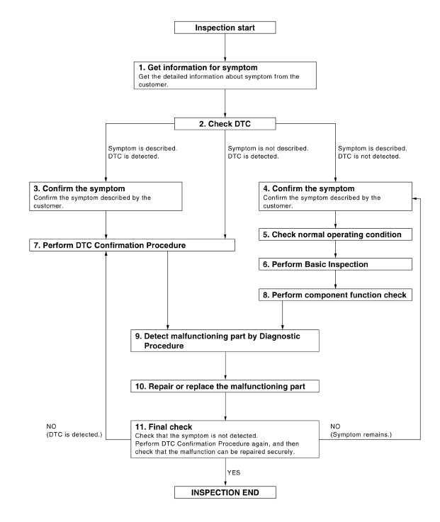
WORK FLOW

DETAILED FLOW
1. GET INFORMATION FOR SYMPTOM
Get the detailed information from the customer about the symptom (the condition and the environment when the incident/malfunction occurred).
2. CHECK DTC
- Check DTC.
- Perform the following procedure if DTC is displayed.
- Record DTC and freeze frame data (Print them out with CONSULT.)
- Erase DTC.
- Study the relationship between the cause detected by DTC and the symptom described by the customer.
- Check related service bulletins for information.
Is any symptom described and any DTC detected?
Symptom is described, DTC is detected.
Symptom is not described, DTC is detected.
Symptom is described, DTC is not detected.
3. CONFIRM THE SYMPTOM
Confirm the symptom described by the customer.
Connect CONSULT to the vehicle in "DATA MONITOR" mode and check real time diagnosis results.
Verify relation between the symptom and the condition when the symptom is detected.
4. CONFIRM THE SYMPTOM
Confirm the symptom described by the customer.
Connect CONSULT to the vehicle in "DATA MONITOR " mode and check real time diagnosis results.
Verify relation between the symptom and the condition when the symptom is detected.
5. CHECK NORMAL OPERATING CONDITION
Check normal operating condition. Refer to ADP-166, "Description".
6. PERFORM BASIC INSPECTION
Isolate the malfunctioning part with the basic inspection. Refer to ADP-8, "Preliminary Check".
7. PERFORM DTC CONFIRMATION PROCEDURE
Perform DTC Confirmation Procedure for the displayed DTC, and then check that DTC is detected again.
At this time, always connect CONSULT to the vehicle, and check diagnostic results in real time.
If two or more DTCs are detected, refer to BCS-63, "DTC Inspection Priority Chart" and determine trouble diagnosis order.
NOTE:
- Freeze frame data is useful if the DTC is not detected.
- Perform Component Function Check if DTC Confirmation Procedure is
not included in Service Manual. This simplified check procedure is an
effective alternative though DTC cannot be detected during this check.
If the result of Component Function Check is NG, it is the same as the detection of DTC by DTC Confirmation Procedure.
Is DTC detected?
8. PERFORM COMPONENT FUNCTION CHECK
Perform the component function check for the isolated malfunctioning part.
9. DETECT MALFUNCTIONING PART BY DIAGNOSTIC PROCEDURE
Inspect according to diagnostic procedure of the system.
10. REPAIR OR REPLACE THE MALFUNCTIONING PART
- Repair or replace the malfunctioning part.
- Reconnect parts or connectors disconnected during diagnostic procedure.
11. FINAL CHECK
Check that the symptom is not detected. Perform DTC Confirmation Procedure or Component Function Check again, and then check that the malfunction has been repaired securely.
Has the malfunction been repaired?
 Basic inspection
...
 Inspection and adjustment
Preliminary Check
1. FOREIGN OBJECTS
Check the following:
objects on or behind the seats that could cause binding
objects under the seats that may be interfering with the seat's
moving part ...
Other materials:
Precaution
PRECAUTIONS
Precaution for Supplemental Restraint System (SRS) "AIR BAG" and "SEAT
BELT
PRE-TENSIONER"
The Supplemental Restraint System such as "AIR BAG" and "SEAT BELT
PRE-TENSIONER", used along
with a front seat belt, helps to reduce the risk or severity of injury to t ...
Loading tips
The GVW must not exceed GVWR
or GAWR as specified on the
F.M.V.S.S./C.M.V.S.S. certification
label.
Do not load the front and rear axle to
the GAWR. Doing so will exceed the
GVWR.
WARNING
Properly secure all cargo with
ropes or straps to help prevent it
from sliding or shif ...
Rear view camera
Removal and Installation
REMOVAL
Remove the license plate finisher. Refer to EXL-166, "Removal and
Installation".
Remove trunk lid finisher. Refer to INT-36, "Exploded View".
Disconnect the rear view camera connector (B), press the rear
view camera tab (A) and remove the rear view c ...
Nissan Maxima Owners Manual
- Illustrated table of contents
- Safety-Seats, seat belts and supplemental restraint system
- Instruments and controls
- Pre-driving checks and adjustments
- Monitor, climate, audio, phone and voice recognition systems
- Starting and driving
- In case of emergency
- Appearance and care
- Do-it-yourself
- Maintenance and schedules
- Technical and consumer information
Nissan Maxima Service and Repair Manual
0.006
