Nissan Maxima Service and Repair Manual: Tilt switch
Description
ADP steering switch (tilt switch) is equipped to the steering column. The operation signal is input to the automatic drive positioner control unit when the tilt switch is operated.
Component Function Check
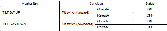
1. CHECK FUNCTION
- Select "TILT SW-UP", "TILT SW-DOWN" in "DATA MONITOR" mode with CONSULT.
- Check tilt switch signal under the following conditions.
Diagnosis Procedure
Regarding Wiring Diagram information, refer to ADP-150, "Wiring Diagram".
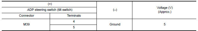
1. CHECK TILT SWITCH SIGNAL
- Turn ignition switch OFF.
- Disconnect ADP steering switch (tilt switch).
- Check voltage between ADP steering switch harness connector and ground.
2. CHECK TILT SWITCH CIRCUIT
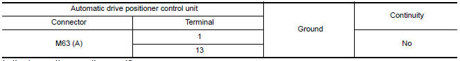
- Disconnect automatic drive positioner control unit.
- Check continuity between automatic drive positioner control unit harness connector and ADP steering switch harness connector.
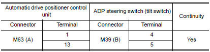
- Check continuity between automatic drive positioner control unit harness connector and ground.
3. CHECK TILT SWITCH
Refer to ADP-59, "Component Inspection".
4. CHECK INTERMITTENT INCIDENT
Refer to GI-41, "Intermittent Incident".
Component Inspection
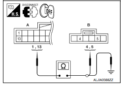
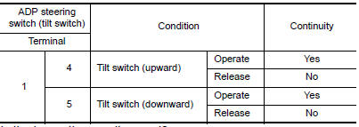
1. CHECK TILT SWITCH
- Turn ignition switch OFF.
- Disconnect ADP steering switch (tilt switch).
- Check continuity between ADP steering switch terminals
 Lifting switch (rear)
Description
Lifting switch (rear) is equipped to the power seat switch LH on the seat
frame. The operation signal is inputted to the driver seat control unit when
the lifting switch (rear) is ope ...
 Telescopic switch
Description
ADP steering switch (telescopic switch) is equipped to the steering column.
The operation signal is input to the automatic drive positioner control unit
when the telescopic switch is ...
Other materials:
RGB (G: green) signal circuit
Description
Transmit the image displayed with AV control unit with RGB signal to the
display unit.
Diagnosis Procedure
1.CHECK CONTINUITY RGB (G: GREEN) SIGNAL CIRCUIT
Turn ignition switch OFF.
Disconnect display unit connector M141 and AV control unit
connector M117.
Check conti ...
Parking, license plate and tail lamps system
Wiring Diagram
...
Tweeter
Description
The AV control unit sends audio signals to the BOSE speaker amp. The BOSE
speaker amp. amplifies the
audio signals before sending them to the tweeters using the audio signal
circuits.
Diagnosis Procedure
1.CONNECTOR CHECK
Check the AV control unit, BOSE speaker amp. and speaker ...
Nissan Maxima Owners Manual
- Illustrated table of contents
- Safety-Seats, seat belts and supplemental restraint system
- Instruments and controls
- Pre-driving checks and adjustments
- Monitor, climate, audio, phone and voice recognition systems
- Starting and driving
- In case of emergency
- Appearance and care
- Do-it-yourself
- Maintenance and schedules
- Technical and consumer information
Nissan Maxima Service and Repair Manual

0.0062