Nissan Maxima Service and Repair Manual: Wheel sensors
Exploded View - Front Wheel Sensor
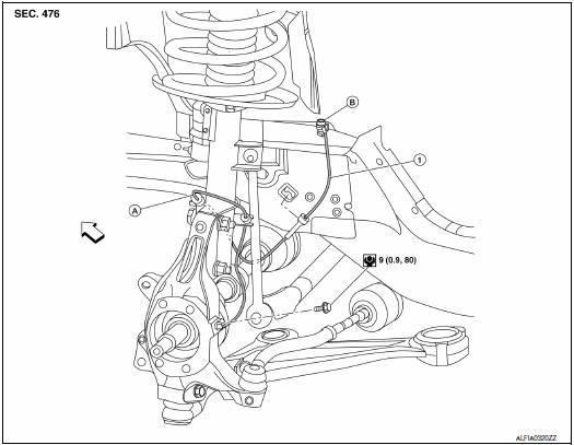
- Front wheel sensor
- Color line (slant line)
- Front wheel sensor harness connector
 Front
Front
Removal and Installation - Front Wheel Sensor
CAUTION:
- Be careful not to damage wheel sensor edge and sensor rotor teeth.
- When pulling out the wheel sensor, be careful to turn it as little as possible. Do not pull on the wheel sensor harness.
- Check if foreign objects such as iron fragments are adhered to the pick-up part of the sensor or to the inside of the hole for the wheel sensor, or if a foreign object is caught in the surface of the mating surface for the wheel sensor. Repair as necessary and then install the wheel sensor.
REMOVAL
- Remove the front wheel and tire using power tools. Refer to WT-60, "Adjustment".
- Partially remove front wheel fender protector and reposition out of the way. Refer to EXT-24, "Removal and Installation".
- Disconnect the harness connector from the front wheel sensor.
- Remove the front wheel sensor harness from the brackets.
- Remove the front wheel sensor bolt and front wheel sensor from the front wheel hub and bearing assembly.
INSTALLATION
Installation is in the reverse order of removal.
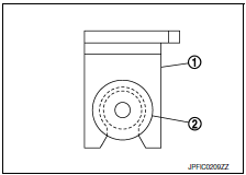
CAUTION: Do not twist rear wheel sensor harness when installing rear wheel sensor. Check that grommet (2) is fully inserted to bracket (1). Check that rear wheel sensor harness is not twisted after installation.
Exploded View - Rear Wheel Sensor
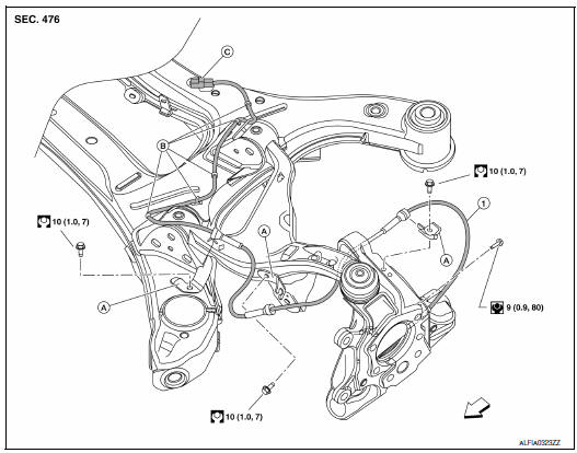
- Rear wheel sensor
- Rear wheel sensor bracket
- Clip
- Rear wheel sensor harness connector
 Front
Front
Removal and Installation - Rear Wheel Sensor
CAUTION:
- Be careful not to damage wheel sensor edge and sensor rotor teeth.
- When removing the front or rear wheel hub, first remove the wheel sensor from the wheel hub. Failure to do so may result in damage to the wheel sensor wires making the sensor inoperative.
- Pull out the wheel sensor, being careful to turn it as little as possible. Do not pull on the wheel sensor harness.
- Before installation, check if foreign objects such as iron fragments are adhered to the pick-up part of the sensor or to the inside of the hole in the wheel hub for the wheel sensor, or if a foreign object is caught in the surface of the mating surface for the sensor rotor. Clean as necessary and then install the wheel sensor.
REMOVAL
- Remove the rear wheel and tire using power tools. Refer to WT-60, "Adjustment".
- Remove the rear stabilizer bar clamps and bushings. Position the stabilizer bar out of the way. Refer to RSU-15, "Exploded View".
- Disconnect the harness connector from the rear wheel sensor.
- Remove the rear wheel sensor harness from the brackets.
- Remove the rear wheel sensor bolt and rear wheel sensor from the rear wheel hub and bearing assembly
INSTALLATION
Installation is in the reverse order of removal.
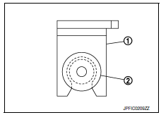
CAUTION: Do not twist rear wheel sensor harness when installing rear wheel sensor. Check that grommet (2) is fully inserted to bracket (1). Check that rear wheel sensor harness is not twisted after installation.

 Sensor rotor
Removal and Installation - Front Sensor Rotor
The front wheel sensor rotor is an integral part of the wheel hub and bearing
assembly and cannot be disassembled.
Removal and Installation - Rear Sen ...
Other materials:
Front wiper does not operate
Description
The front wiper does not operate under any operation conditions
Diagnosis Procedure
1. CHECK WIPER RELAY OPERATION
IPDM E/R AUTO ACTIVE TEST
Start IPDM E/R auto active test. Refer to PCS-11, "Diagnosis
Description".
Check that the front wiper operates at the LO/HI operation. ...
Center console assembly
Exploded View
Center console side finisher (LH)
Center console finisher
CVT finisher
Center console storage bin
Center console screw cover (LH)
Center console rear finisher
Center console screw cover (RH)
Center console
Center console lid assembly
Cup holder
Center cons ...
Navigation System
Turn-by-turn route guidance can be displayed on
the vehicle information display.
To view turn-by-turn route guidance on the vehicle
information display, use or
and
scroll to on the vehicle
information display
menu.
City view
City view shows representation of intersections
with ...
Nissan Maxima Owners Manual
- Illustrated table of contents
- Safety-Seats, seat belts and supplemental restraint system
- Instruments and controls
- Pre-driving checks and adjustments
- Monitor, climate, audio, phone and voice recognition systems
- Starting and driving
- In case of emergency
- Appearance and care
- Do-it-yourself
- Maintenance and schedules
- Technical and consumer information
Nissan Maxima Service and Repair Manual

0.0058