Nissan Maxima Service and Repair Manual: U1000 Can comm circuit
Description
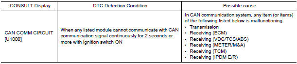
DTC Logic
DTC DETECTION LOGIC
NOTE: U1000 can be set if a module harness was disconnected and reconnected, perhaps during a repair. Confirm that there are actual CAN diagnostic symptoms and a present DTC by performing the Self Diagnostic Result procedure.
Diagnosis Procedure
1. PERFORM SELF DIAGNOSTIC
- Turn ignition switch ON and wait for 2 seconds or more.
- Check "SELF- DIAG RESULTS ".

 U1010 Control unit (CAN)
DTC Logic
DTC DETECTION LOGIC
Diagnosis Procedure
1. REPLACE BCM
When DTC U1010 is detected, replace BCM. ...
Other materials:
Programming trouble-diagnosis
If the HomeLink does not quickly learn the
hand-held transmitter information:
replace the hand-held transmitter batteries
with new batteries.
position the hand-held transmitter with its
battery area facing away from the
HomeLink surface.
press and hold both the HomeLink and
hand-hel ...
Diagnosis system (BCM)
COMMON ITEM
COMMON ITEM : CONSULT Function (BCM - COMMON ITEM)
APPLICATION ITEM
CONSULT performs the following functions via CAN communication with BCM.
SYSTEM APPLICATION
BCM can perform the following functions.
HEADLAMP
HEADLAMP : CONSULT Function (BCM - HEAD LAMP)
DATA MONITOR
ACTI ...
Turn signal and hazard warning lamp system
Wiring Diagram
...
Nissan Maxima Owners Manual
- Illustrated table of contents
- Safety-Seats, seat belts and supplemental restraint system
- Instruments and controls
- Pre-driving checks and adjustments
- Monitor, climate, audio, phone and voice recognition systems
- Starting and driving
- In case of emergency
- Appearance and care
- Do-it-yourself
- Maintenance and schedules
- Technical and consumer information
Nissan Maxima Service and Repair Manual

0.0057