Nissan Maxima Service and Repair Manual: Diagnosis and repair work flow
Work Flow
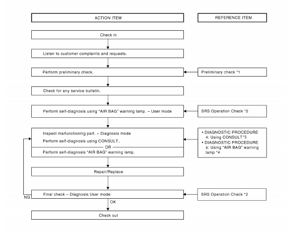
OVERALL SEQUENCE
DETAILED WORK FLOW
1.CUSTOMER INFORMATION
Get detailed information from the customer about the symptom.
2.PRELIMINARY CHECK
Perform preliminary check.
3.TECHNICAL SERVICE BULLETINS
Check for technical service bulletins.
4.USER MODE
Perform self-diagnosis using the "AIR BAG" warning lamp in User mode.
5.SELF-DIAGNOSIS
Perform SELF-DIAGNOSIS.
6.REPLACE PART
Replace the malfunctioning part.
7.FINAL CHECK
Check SRS using Diagnosis mode and User mode.
 Basic inspection
...
 Intermittent incident
Inspection Procedure
INTERMITTENT TROUBLE
An intermittent incident may have occured in the past but is not being
detected currently. This DTC will not bedetected on SELF DIAG [CURRENT], but
may ...
Other materials:
P0130, P0150 A/F sensor 1
Description
The air fuel ratio (A/F) sensor 1 is a planar one-cell limit current sensor.
The sensor element of the A/F sensor 1 is composed an electrode
layer, which transports ions. It has a heater in the element.
The sensor is capable of precise measurement = 1, but also in the
lean ...
Change intervals
The oil and oil filter change intervals for your
engine are based on the use of the specified
quality oils and filters. Using engine oil and filters
that are not of the specified quality, or exceeding
recommended oil and filter change intervals
could reduce engine life. Damage to the engine
ca ...
AMP on signal circuit
Description
When the audio system is turned on, a voltage signal is supplied from the AV
control unit to the BOSE speaker
amp. When this signal is received, the BOSE speaker amp. will turn on.
Diagnosis Procedure
1.CHECK AMP ON SIGNAL (BOSE SPEAKER AMP)
Turn audio system ON.
Check v ...
Nissan Maxima Owners Manual
- Illustrated table of contents
- Safety-Seats, seat belts and supplemental restraint system
- Instruments and controls
- Pre-driving checks and adjustments
- Monitor, climate, audio, phone and voice recognition systems
- Starting and driving
- In case of emergency
- Appearance and care
- Do-it-yourself
- Maintenance and schedules
- Technical and consumer information
Nissan Maxima Service and Repair Manual

0.0069