Nissan Maxima Service and Repair Manual: Parking brake control
Exploded View
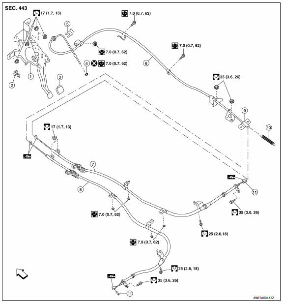
- Parking brake pedal
- Parking brake switch
- Pedal pad
- Adjusting nut
- Lock plate
- Front cable
- Rear cable (RH)
- Rear cable (LH)
- Equalizer
- Spring
- Pin
 Front
Front
Removal and Installation
REMOVAL
- Remove rear wheel and tire using power tool. Refer to WT-60, "Adjustment".
- Remove instrument lower panel LH.
- Remove lower knee protector (LH). Refer to IP-10, "Exploded View".
- Disconnect parking brake switch connector.
- Remove adjusting nut and discard, then loosen the front cable.
CAUTION: Do not reuse adjusting nut.
- Remove parking brake pedal nuts and remove the parking brake pedal.
- Remove center console. Refer to IP-14, "Removal and Installation".
- Reposition the floor carpet aside.
- Separate the LH and RH rear cables from the equalizer then remove the front cable.
- Remove the front exhaust tube and the center exhaust tube. Refer to EX-5, "Removal and Installation".
- Remove the exhaust center tube heat insulator.
- Remove the rear brake disc rotors. Refer to BR-36, "Removal and Installation of Brake Caliper and Rotor".
- Disconnect the LH and RH rear cables from the toggle lever. Refer to PB-8, "Exploded View".
- Remove the LH and RH rear cable bolts and nuts, then remove the LH and RH rear cables.
INSTALLATION
Installation is in the reverse order of removal.
CAUTION: Do not reuse adjusting nut.
- Refer to PB-6, "Exploded View" for torque specifications.
- Adjust parking brake.

 Parking brake shoe
Exploded View
Back plate
Parking brake shoe (front)
Adjuster
Adjuster spring
Return spring
Anti-rattle spring
Retainer
Anti-rattle pin
Toggle lever
Parking brake shoe ( ...
Other materials:
Door key cylinder switch
Description
The main power window and door lock/unlock switch detects condition of the
door key cylinder switch and
transmits to BCM as the LOCK or UNLOCK signal.
Component Function Check
1.CHECK DOOR KEY CYLINDER SWITCH INPUT SIGNAL
Check KEY CYL UN-SW, KEY CYL UN-SW in "DATA MONITOR" mode ...
P0845 transmission fluid pressure SEN/SW B
Description
The primary pressure sensor detects primary pressure of CVT and sends a
signal to the TCM.
DTC Logic
DTC DETECTION LOGIC
DTC CONFIRMATION PROCEDURE
NOTE:
Immediately after performing any "DTC CONFIRMATION PROCEDURE", always turn
ignition switch OFF.
Then wait at least 10 ...
In-vehicle sensor
Removal and Installation
REMOVAL
Remove the instrument lower panel LH. Refer to IP-19, "Removal and
Installation".
Remove the in-vehicle sensor screw and the in-vehicle sensor.
INSTALLATION
Installation is in the reverse order of removal.
CAUTION:
Make sure that the asp ...
Nissan Maxima Owners Manual
- Illustrated table of contents
- Safety-Seats, seat belts and supplemental restraint system
- Instruments and controls
- Pre-driving checks and adjustments
- Monitor, climate, audio, phone and voice recognition systems
- Starting and driving
- In case of emergency
- Appearance and care
- Do-it-yourself
- Maintenance and schedules
- Technical and consumer information
Nissan Maxima Service and Repair Manual

0.0075