Nissan Maxima Service and Repair Manual: Parking brake shoe
Exploded View
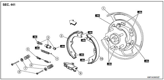
- Back plate
- Parking brake shoe (front)
- Adjuster
- Adjuster spring
- Return spring
- Anti-rattle spring
- Retainer
- Anti-rattle pin
- Toggle lever
- Parking brake shoe (rear)
 Front
Front
 Apply PBC (Poly Butyl Cuprysil)
grease or silicone based grease
Apply PBC (Poly Butyl Cuprysil)
grease or silicone based grease
Removal and Installation
REMOVAL
WARNING:
- Clean brakes with a vacuum dust collector to minimize the hazard of air borne particles or other materials.
- Clean dust on disc rotor and back plate using a vacuum dust collector. Do not blow with compressed air.
- Remove rear wheel and tire using power tool. Refer to WT-60, "Adjustment".
- Remove brake caliper torque member bolts, leaving brake hose attached, reposition the caliper aside with wire. Refer to BR-36, "Exploded View of Brake Caliper".
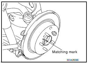
- With the parking brake pedal in the fully released position, remove the disc rotor. CAUTION: Put matching marks on both disc rotor and wheel hub when removing disc rotor. If the disc rotor cannot be removed, remove as follows:
- Secure the disc rotor in place with wheel nuts and remove adjuster hole plug.
- Rotate adjuster (1) in direction (B) to retract and loosen brake shoe, using suitable tool as shown.
- Remove anti-rattle pins, retainers, anti-rattle springs, return spring and adjuster spring.
- Remove parking brake shoes, adjuster assembly, and toggle lever.
INSPECTION AFTER REMOVAL
Lining Thickness Inspection
- Check thickness of lining.
Standard thickness (new) (A) : Refer to PB-11, "Parking
Drum Brake".
Wear limit thickness (A) : Refer to PB-11, "Parking
Drum Brake".
Disc Rotor Inner Diameter Inspection
- Check inner diameter of drum (in disc).
Standard inner diameter (new) : Refer to PB-11, "Parking
Drum Brake".
Wear limit of inner diameter : Refer to PB-11, "Parking
Drum Brake".
Other Inspections
- Check the following:
- Lining for excessive wear, damage, and peeling.
- Shoe sliding surface for excessive wear and damage.
- Anti-rattle pin for excessive wear and corrosion.
- Return spring and adjuster spring for sagging.
- Make sure that adjuster moves smoothly.
- Visually check the inside of drum for excessive wear, cracks, and damage.
- Replace with new parts as necessary.
INSTALLATION
Installation is in the reverse order of removal.
- Refer to PB-8, "Exploded View" and apply PBC (Poly Butyl Cuprysil) grease or silicone-based grease to the specified points during installation.
- Assemble adjusters so that threaded part is expanded when rotating it in the direction as shown.
- Shorten adjuster by rotating it the opposite as shown
- Check parking brake shoe sliding surface and drum inner surface for grease. Wipe off all grease adhering to the friction surfaces.
ADJUSTMENT
After replacing the parking brake shoes or disc rotors, or if the parking brake does not function properly, perform the break-in operation as follows.
- Adjust parking brake pedal stroke to the specified amount. Refer to PB-4, "On-Vehicle Service".
- Perform parking brake break-in (drag run) operation by driving and performing the following steps:
- Drive forward at a constant speed of approximately 40 km/h (25 mph).
- Apply the parking brake for approximately 5 - 15 seconds at an operating force of approximately 150 - 199 N (15 - 20 kg, 34 - 45 lb).
CAUTION:
- To prevent lining from getting too hot, allow cool off period of approximately 5 minutes after every break-in operation.
- Do not perform excessive break-in operations, because it may cause uneven or early wear of lining.
- After break-in operation, check that the parking brake pedal stroke is at specification and adjust again as necessary. Refer to PB-4, "On-Vehicle Service".
 Parking brake control
Exploded View
Parking brake pedal
Parking brake switch
Pedal pad
Adjusting nut
Lock plate
Front cable
Rear cable (RH)
Rear cable (LH)
Equalizer
Spring
Pin
...
 Service data and specifications (SDS)
Parking Brake Control
Parking Drum Brake
...
Other materials:
On board diagnostic (OBD) system
Trouble Diagnosis Introduction
CAUTION:
Do not use electrical test equipment on any circuit related to
the SRS unless instructed to do so inthis Service Manual. SRS wiring
harnesses can be identified by yellow and/or orange harness connectors.
Do not attempt to repair, splice or modify ...
Shift lock release
If the battery charge is low or discharged, the
shift lever may not be moved from the P (Park)
position even with the brake pedal depressed
and the shift lever button pressed.
It will be necessary to jump start or have your
battery charged, For additional information, refer
to "Jump star ...
P0182, P0183 FTT sensor
Description
The fuel tank temperature sensor is used to detect the fuel temperature
inside the fuel tank. The sensor modifies a voltage signal from
the ECM. The modified signal returns to the ECM as the fuel temperature
input. The sensor uses a thermistor which is sensitive to the
chang ...
Nissan Maxima Owners Manual
- Illustrated table of contents
- Safety-Seats, seat belts and supplemental restraint system
- Instruments and controls
- Pre-driving checks and adjustments
- Monitor, climate, audio, phone and voice recognition systems
- Starting and driving
- In case of emergency
- Appearance and care
- Do-it-yourself
- Maintenance and schedules
- Technical and consumer information
Nissan Maxima Service and Repair Manual

0.0077