Nissan Maxima Service and Repair Manual: Passenger side door mirror defogger
Description
Heats the heating wire with the power supply from the rear window defogger relay to prevent the door mirror from fogging up.
Component Function Check
1.CHECK DOOR MIRROR DEFOGGER RH
Check that the heating wire of door mirror defogger RH is heated when turning the rear window defogger switch ON.
Diagnosis Procedure
1. CHECK POWER SUPPLY CIRCUIT
- Turn ignition switch OFF.
- Disconnect door mirror RH.
- Turn ignition switch ON.
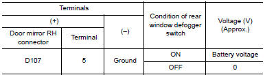
- Check voltage between door mirror RH harness connector D107 terminal 5 and ground.
2. CHECK GROUND CIRCUIT
- Turn ignition switch OFF.
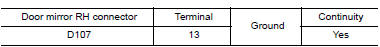
- Check continuity between door mirror RH harness connector D107 terminal 13 and ground.
3. CHECK PASSENGER SIDE DOOR MIRROR DEFOGGER
Check door mirror defogger RH.
4. CHECK INTERMITTENT INCIDENT
Check intermittent incident
Component Inspection
1. CHECK DOOR MIRROR DEFOGGER RH
- Turn ignition switch OFF.
- Disconnect door mirror RH.
- Check continuity between door mirror terminals 5 and 13.
 Driver side door mirror defogger
Description
Heats the heating wire with the power supply from the rear window defogger
relay to prevent the door mirror
from fogging up.
Component Function Check
1. CHECK DOOR MIRROR DEFOGGER L ...
 ECU diagnosis information
BCM (BODY CONTROL MODULE)
Reference Value
NOTE:
The Signal Tech II Tool (J-50190) can be used to perform the following
functions. Refer to the Signal Tech II
User Guide for additional informat ...
Other materials:
B210E starter relay
DTC Logic
DTC DETECTION LOGIC
NOTE:
If DTC B210E is displayed with DTC
U1000, first perform the trouble diagnosis for DTC U1000. Refer to
SEC-29, "DTC Logic".
If DTC B210E is displayed with DTC
U1010, first perform the trouble diagnosis for DTC U1010. Refer to
SEC-30, "D ...
Owner's Manual/Service Manual order information
Genuine NISSAN Service Manuals for this model
year and prior can be purchased. A Genuine
NISSAN Service Manual is the best source of
service and repair information for your vehicle.
This manual is the same one used by the factorytrained
technicians working at NISSAN dealerships.
Genuine NI ...
Both side headlamps (LO) are not turned on
Description
The headlamps (both sides) do not turn ON in any lighting switch setting.
Diagnosis Procedure
1.CHECK COMBINATION SWITCH (LIGHTING AND TURN SIGNAL SWITCH)
Check the combination switch (lighting and turn signal switch
2.CHECK HEADLAMP (LO) REQUEST SIGNAL INPUT
CONSULT DATA MONITOR
...
Nissan Maxima Owners Manual
- Illustrated table of contents
- Safety-Seats, seat belts and supplemental restraint system
- Instruments and controls
- Pre-driving checks and adjustments
- Monitor, climate, audio, phone and voice recognition systems
- Starting and driving
- In case of emergency
- Appearance and care
- Do-it-yourself
- Maintenance and schedules
- Technical and consumer information
Nissan Maxima Service and Repair Manual

0.0055