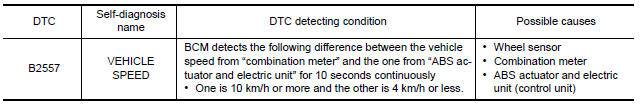
Nissan Maxima Service and Repair Manual: B2557 vehicle speed
Description
BCM receives the 2 vehicle speed signals via CAN communication. One signal is transmitted by the "combination meter". Another signal is transmitted by "ABS actuator and electric unit (control unit)". BCM compares both signals to detect the vehicle speed.
DTC Logic
DTC DETECTION LOGIC
NOTE:
-
If DTC B2557 is displayed with DTC U1000, first perform the trouble diagnosis for DTC U1000. Refer to SEC-29, "DTC Logic".
-
If DTC B2557 is displayed with DTC U1010, first perform the trouble diagnosis for DTC U1010. Refer to SEC-30, "DTC Logic".
DTC CONFIRMATION PROCEDURE
1.PERFORM DTC CONFIRMATION PROCEDURE
-
Drive the vehicle at the vehicle speed of 10 km/h or more and wait for at least 10 seconds.
-
Check "Self Diagnostic Result" with CONSULT.
Diagnosis Procedure
1.CHECK DTC WITH "ABS ACTUATOR AND ELECTRIC UNIT (CONTROL UNIT)"
Check "Self Diagnostic Result" with CONSULT. Refer to BRC-82, "DTC No. Index".
2.CHECK COMBINATION METER.
Check combination meter. Refer to MWI-4, "Work Flow".
Inspection End.
 B2556 push-button ignition switch
Description
The switch that changes the power supply position. BCM
maintains the power supply position status. BCM
changes the power supply position with the operation of the push-button ignition ...
 B2560 starter control relay
Description
Starter control relay, integrated in IPDM E/R, permits
the starter relay operation when in N or P position. It is
installed in parallel with the starter relay.
DTC Logic
DTC DETECTI ...
Other materials:
Navigation system
System Diagram
System Description
NOTE:
Refer to NAVI System Owner's Manual for system operation.
The navigation system periodically calculates the vehicle's current position
according to the following three
signals: Travel distance of the vehicle as determined by the vehicle s ...
Normal operating condition
Description
The majority of the audio concerns are the result of outside causes (bad CD,
electromagnetic interference,
etc.).
NOISE
The following noise results from variations in field strength, such as fading
noise and multi-path noise, or
external noise from trains and other sources. I ...
Answer back horn feature
If desired, the answer back horn feature can be
deactivated using the Intelligent Key. When it is
deactivated and the LOCK
button is
pushed, the hazard indicator lights flash twice.
When the UNLOCK button is pushed,
neither
the hazard indicator lights nor the horn operates.
NO ...
Nissan Maxima Owners Manual
- Illustrated table of contents
- Safety-Seats, seat belts and supplemental restraint system
- Instruments and controls
- Pre-driving checks and adjustments
- Monitor, climate, audio, phone and voice recognition systems
- Starting and driving
- In case of emergency
- Appearance and care
- Do-it-yourself
- Maintenance and schedules
- Technical and consumer information
Nissan Maxima Service and Repair Manual

0.0052