Nissan Maxima Service and Repair Manual: Aux in jack
Removal and Installation
REMOVAL
- Remove the center console. Refer to IP-14, "Removal and Installation".
- Remove the center console bin box.
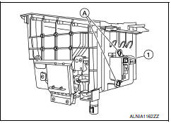
- Remove the auxiliary input jacks screws (A), then remove the auxiliary input jacks (1).
INSTALLATION
Installation is in the reverse order of removal.
 USB connector
Removal and Installation
REMOVAL
Remove the center console assembly. Refer to IP-14, "Removal and
Installation".
Release the pawl from the back of the center console to remove the
USB i ...
 Front tweeter
Removal and Installation
REMOVAL
Remove the front pillar finisher. Refer to INT-24, "Removal and
Installation".
Remove the front tweeter speaker grille. Refer to IP-10, "Exploded
View". ...
Other materials:
Bose speaker AMP
Removal and Installation
Bose speaker amp.
Screws
REMOVAL
NOTE: If removing the BOSE speaker amp.
bracket, it is necessary to remove the parcel shelf finisher. The BOSE
speaker amp. can be removed without removing the BOSE speaker amp. bracket.
Disconnect the battery negative ...
The door open warning continues displaying, or does not display
Description
The door ajar warning is displayed even though
all of the doors and the trunk are closed.
The door ajar warning is not displayed even
though a door or the trunk is ajar.
Diagnosis Procedure
1.CHECK BCM INPUT SIGNAL
Connect CONSULT and check the BC ...
Brake tube and hose
Hydraulic Circuit
Actuator
Master cylinder
Brake booster
Connector
Union bolt
18.2 N*m (1.9 kg-m, 13 ft-lb)
Flare nut M12
22.1 N*m (2.3 kg-m, 16 ft-lb)
Flare nut M10
16.2 N*m (1.7 kg-m, 12 ft-lb)
CAUTION:
All hoses and piping (tubes) must be free fr ...
Nissan Maxima Owners Manual
- Illustrated table of contents
- Safety-Seats, seat belts and supplemental restraint system
- Instruments and controls
- Pre-driving checks and adjustments
- Monitor, climate, audio, phone and voice recognition systems
- Starting and driving
- In case of emergency
- Appearance and care
- Do-it-yourself
- Maintenance and schedules
- Technical and consumer information
Nissan Maxima Service and Repair Manual

0.0085