Nissan Maxima Owners Manual: Shift lock release
If the battery charge is low or discharged, the shift lever may not be moved from the P (Park) position even with the brake pedal depressed and the shift lever button pressed.
It will be necessary to jump start or have your battery charged, For additional information, refer to "Jump starting" in the "In case of emergency" section of this manual. It is recommended that you visit a NISSAN dealer or a professional towing service.
To move the shift lever, complete the following procedure: 1. Push the ignition switch to the LOCK position.
2. Apply the parking brake.
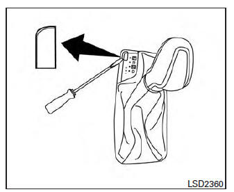
3. Using a protective cloth on the tip of a small (1/8 inch or 3 mm) flat-head screwdriver, remove the shift lock release cover.
- If available, a plastic trim tool can also be used.
4. Insert the car key into the shift lock release slot and press straight down. A small screwdriver or small trim tool may also be used.
- For additional information, refer to "NISSAN Intelligent Key" in the "Predriving checks and adjustments" section of this manual.
5. Move the shift lever to the N (Neutral) position while holding down the shift lock release.
6. Push the ignition switch to the ON position to unlock the steering wheel. Now the vehicle may be moved to the desired location.
If the shift lever cannot be moved out of P (Park), have the transmissions checked as soon as possible.
It is recommended that you visit a NISSAN dealer for this service.
CAUTION
Make sure to take extra care during the removal of the shift lock cap as this part is easily damaged.
WARNING
If the shift lever cannot be moved from the P (Park) position while the engine is running and the brake pedal is depressed, the stop lights may not work. Malfunctioning stop lights could cause an accident injuring yourself and others.
Accelerator downshift - in D (Drive) position and manual shift mode
For passing or hill climbing, depress the accelerator pedal to the floor. This shifts the transmission down into lower range, depending on the vehicle speed.
High fluid temperature protection mode
This transmission has a high fluid temperature protection mode. If the fluid temperature becomes too high (for example, when climbing steep grades in high temperatures with heavy loads, such as when towing a trailer), engine power and, under some conditions, vehicle speed will be decreased automatically to reduce the chance of transmission damage. Vehicle speed can be controlled with the accelerator pedal, but the engine and vehicle speed may be limited.
Fail-safe
If the vehicle is driven under extreme conditions, such as excessive wheel spinning and subsequent hard braking, the fail-safe system may be activated. The MIL may come on to indicate the fail-safe mode is activated. For additional information, refer to "Malfunction Indicator Light (MIL)" in the "Instruments and controls" section of this manual. This will occur even if all electrical circuits are functioning properly. In this case, place the ignition switch in the OFF position and wait for 10 seconds. Then place the ignition switch back in the ON position. The vehicle should return to its normal operating condition. If it does not return to its normal operating condition, have the transmission checked and repaired, if necessary. It is recommended that you visit a NISSAN dealer for this service.
WARNING
When the high fluid temperature protection mode or fail-safe operation occurs, vehicle speed may be gradually reduced.
The reduced speed may be lower than other traffic, which could increase the chance of a collision. Be especially careful when driving. If necessary, pull to the side of the road at a safe place and allow the transmission to return to normal operation, or have it repaired if necessary.
 Manual shift mode
The transmission enters the manual shift mode by
moving the shift lever to the left side in the "D"
range. You can select the manual shift range
either by moving the shift lever up or down, or ...
 Parking brake
WARNING
Be sure the parking brake is fully released
before driving. Failure to do so
can cause brake failure and lead to an
accident.
Do not release the parking brake from
outside the ve ...
Other materials:
Both doors mirror defogger don't operate but rear window
defogger operates
Diagnosis Procedure
1. CHECK DOOR MIRROR DEFORGGER FUSE
Check if the following fuse in fuse block (J/B) is blown.
2. CHECK DOOR MIRROR DEFORGGER CIRCUIT
Turn ignition switch OFF.
Disconnect the following harness connectors.
Fuse block (J/B) connector M5
Door mirror LH D4
Door ...
Forward-facing child restraint installation using LATCH
For additional information, refer to all Warnings
and Cautions in the "Child safety" and "Child
restraints" sections of this manual before installing
a child restraint.
Do not use the lower anchors if the combined
weight of the child and the child restraint exceeds
65 lbs (29.5 kg). If the c ...
Microphone
Removal and Installation
REMOVAL
Remove the map lamp assembly. Refer to INL-84, "Removal and
Installation".
Detach the microphone connector (A).
Remove the map lamp covers (1), then remove the map lamp assembly
cover (2).
Release the microphone tabs (A), then remove the micr ...
Nissan Maxima Owners Manual
- Illustrated table of contents
- Safety-Seats, seat belts and supplemental restraint system
- Instruments and controls
- Pre-driving checks and adjustments
- Monitor, climate, audio, phone and voice recognition systems
- Starting and driving
- In case of emergency
- Appearance and care
- Do-it-yourself
- Maintenance and schedules
- Technical and consumer information
Nissan Maxima Service and Repair Manual

0.0064